
A front view of the finished design.
Musings on the Miracle Whip design
A front view of the finished design.
The 'Miracle Whip' design is of interest to people wishing to have a small footprint portable setup. However, looking at the original design published in QST in 2001, it is clear that the rheostat auto transformer design, while innovative, is a stumbling block to home construction of the antenna. It is also self evident that it is difficult to build since the commercial design uses an entirely different approach.
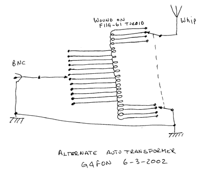
As I said, the autotransformer approach to matching the short whip to the transmitter is innovative, if not original. I looked at this concept and decided that it could be mechanically simplified if the user was to accept two controls, one for coarse tuning, the other for fine tuning. This is the basis of the modified design presented here.
Rather than building a transformer with a tap at each turn, this design relies on a transformer which has one tap per turn for the first four turns, a tap every fourth turn for forty-eight turns and then another four turns tapped each turn. The coarse 12 pole tuning switch is connected to the twelve four turn taps. For the fine tuning a dual ganged 4 pole switch is connected to both the top and the bottom tapped sections.
The design should be easy to duplicate, I have used no specialist parts and takes about an afternoon to put together. The cost, in the UK, was around �10 with components purchased from Maplin, and could be less if you have a well stocked junk box!
The twelve position switch on the lefthand side sets the coarse tuning and
the ganged switch on the righthand side provides the fine tuning
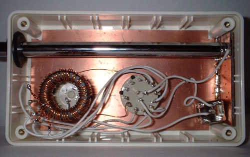
This picture shows the inside of the Whip, this the unit lying on its side.
In the bottom lefthand corner is the coarse tuning switch with the toroid mounted on top.
In the centre is the fine tuning switch and to the right is the BNC connector.
Also note the use of PCB material for a baseplate.
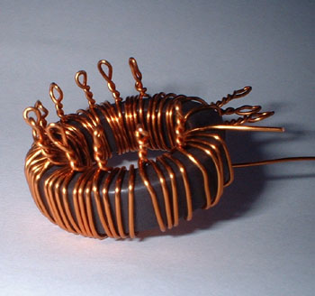
This picture shows a closeup of the toroid with the taps clearly visible
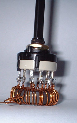
The toroid mounted on the coarse tuning switch.
Note the radial taps in the bottom lefthand corner.
The next job is to solder the toroid to the coarse tuning switch, once finished, it should look similar to the picture above.

The bottom of the whip mounted onto the PCB material
Note that the copper is cut around the screw hole to prevent a short to ground.
The Whip I used required an M4 mounting screw which I soldered to a piece of PCB material. I used the edge of a file to clear the copper around the mounting point to prevent a short to ground, this is clearly visible in the picture above. At the top of the case (not shown), I drilled a hole for the whip and used a rubber grommet for neatness.
I have not gone into the finer details of drilling and mounting the switches or the BNC connector. From the pictures you can get an idea of the positioning, but I will leave it to you to fine tune the ergomonics of your copy of the design! Once the hardware is bolted down, connect up the remaining connections with hookup wire.
Operating this design is similar to the original 'Miracle Whip' design. Once you have selected the band on the FT817, set the fine tuning control to position two or three and rotate the coarse tuning control to achieve the highest background noise, or the strongest signal if you are listening to a station. Next key the rig and use the fine tune control to achieve the lowest SWR. You may find it is necessary to move the coarse tuning a position either way to optimise the SWR reading. Once you have the lowest SWR, note down the settings so that you can quickly QSY to the band again.
It is important to note that this design is only suitable for power levels up to about 10 Watts.
The whip described here will tune up to a respectable SWR on 40 metres and up.
Much has been said about the performance of the 'Miracle Whip' design, but at the end of the day a 48 inch whip is going to be hard pressed to beat most other antennas. My experience is that it does not come close to the performance of the loop antenna's to be found on this site. However, when the bands are in good shape you will make QSO's. During the testing of the design, I work an OK1 on 15 metres (a distance of about 700 miles) for a 439 report, I gave him 559 in exchange. We were both running 5 Watts QRP. Later, on 30 metres, I worked a PA3 who gave me 449 to his 589, again both QRP.
If you have any questions, suggestions or good experiences with the antenna, drop me an email, I will be interested to hear your successes.