Military Wireless in the Midlands
The WS 19 Page

The WS 19 is probably, along with the Command series, one of the best known sets of WW2.
Its amazing though to see just how many different sets and connecting items were made, the
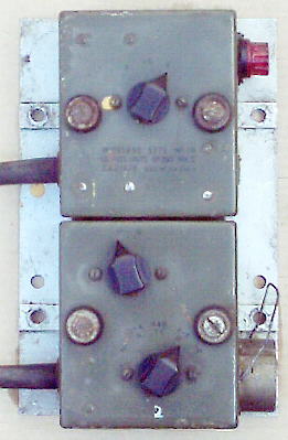
various Mk's of set itself plus all the bits that plug into it. Control boxes in particular are many in
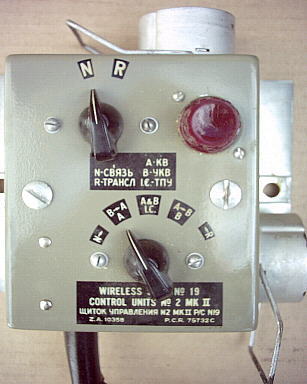
style and use's. Grey, green and blue boxes. Single drop leads, double drop leads, English marking, English and Russian marking,
single and double boxes, interconnection with the WS38, standard 2 wire line, single 12 pin i/o, twin
12 pin i/o, different knobs etc etc. Spares boxes, valve boxes, remote control boxes, etc.
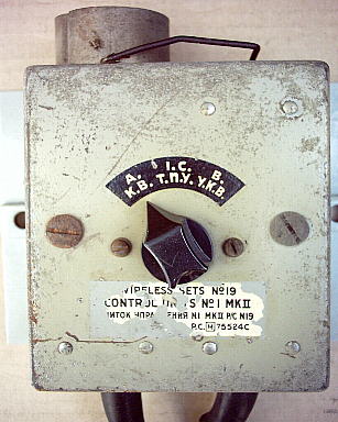
One strange control box arrived here recently, a No 1 Mk2 with Russian marking and a hefty cable
coming out of the top with each core identified obviously for connection to some other
control box. If anyone has any idea as to what installation it goes in, please let me know.
Picture of my Mk III set:
The new MK II as it arrived:


More as the set is tested etc.
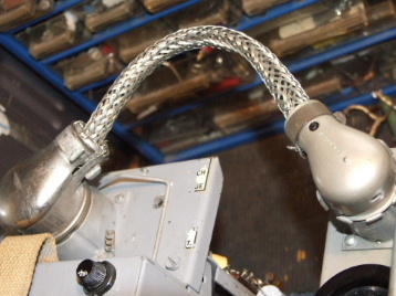
My attempt at making a 12 to 6 armoured connecting lead.
CONTROL BOXES OF ALL SORTS


No1 MkII
No1 Mk 2
No1 Mk2
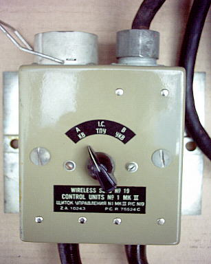
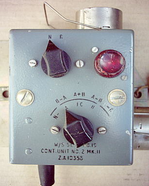
No1 Mk 2
No2 Mk 2
No2 Mk2 (green)

No2 Mk 2 (grey)
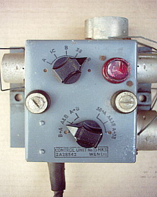
No16 Mk 1/1
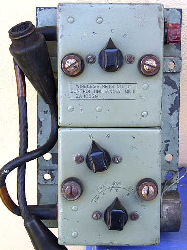
No 3 Mk II

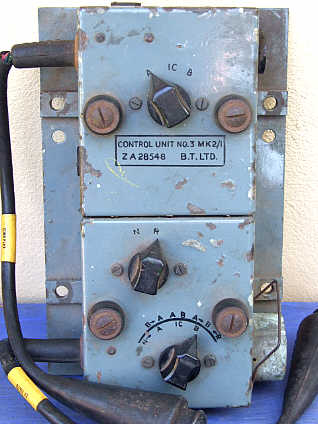
No3BT Mk2
No3C Mk2
No3 Mk2/1
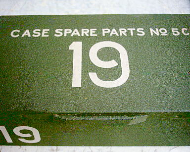

Spares Case 5C
normal green
colour
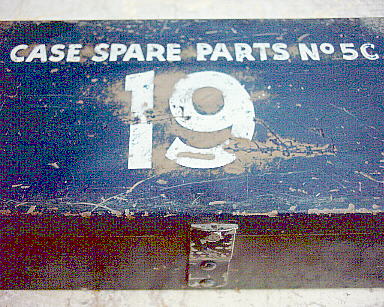
Spares Case 5C
unusual blue
colour. Navy ?
Valve Box 4G
19 or 22 set use


Spares Case 5C
internal photo
with key, fuses & bulbs
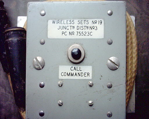
Junction Distribution
Box No3
Power Unit No2
dyno/vib version
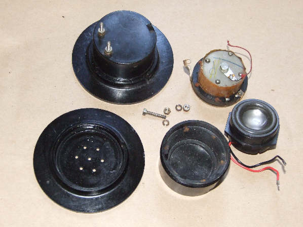
One item often at fault is the Headset/mic combination. This is the twin padded headset with
microphone No4 etc combined into a single drop lead with the 5 pin rubber plug on the end. The usual
fault is that the small loudspaker coils in the headset go open circuit. There is enough space inside
them though to replace the old coil with a modern loudspeaker or insert.

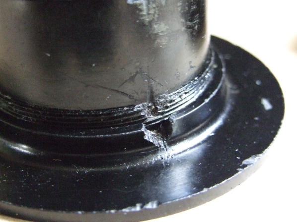
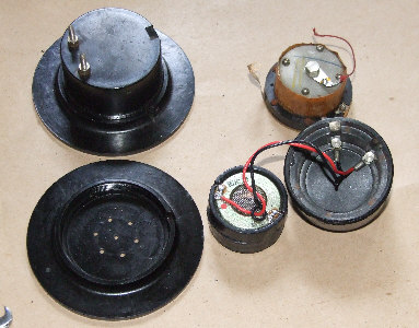
Recently I found another headset with duff phones. Pictures show the replacing of phones with small speakers.
There is a small ball bearing lodged in the thread of the front cover and the speaker housing. I could find no way of removing other than drilling
it out. The first pic shows the resulting hole. With the ball bearing popped out the front disk unscrews from the body part.

The Wireless Set No19
by
Ben Nock
In these past few years of World War Two remembrances, many thoughts about radios and how they were fitted to vehicles and used in campaigns have arisen.
Many collectors and Radio Amateur operators have, over the years, brought new life to many war time sets, those that covered any licensed amateur
frequencies are indeed capable of being fired up in anger once again and actual contacts made on the air.
My own interest in vintage equipment started some 30 years ago with the acquisition of a WS No 19 and an R1155 RAF receiver. Over the years I have
restored many sets and, where possible, have used my amateur radio licence to fire them up on an amateur band and make many interesting contacts.
It is always a good talking point to mention that the QSO (shorthand term for a radio contact) is being made with what is now a 50 or 60 year old
piece of equipment.
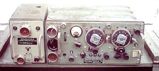
The WS 19 was probably one of the most famous sets of the second world war, used in all theatres where the British were involved, in tanks,
jeeps, on the back of pack animals, up mountains and in deserts. The 19 set was in fact still in use many years after the war, though in later
years as a training set, I even have an example with a REME (Royal Electrical & Mechanical Engineers) workshop stamp on it dated as late as 1962.
This was the date it was last refurbished at the workshops.
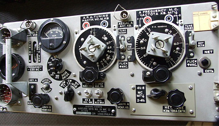
The 19 set was one of the mainstays of British Army communications throughout the second world war, three versions being produced, the MK I, II and
III. The sets covered 2.5 to 6.25 Mhz in the Mk I, and 2 to 8 Mhz in the Mk II and III in two bands, capable of AM (Amplitude Modulation) , MCW
(Modulated Morse Code) and CW (Morse Code) operation. The set in fact contained two systems, the HF system and a VHF unit running on around 230 Mhz
with what is termed a regenerative receiver and AM transmitter.
The HF set was supposed to run around 12 watt, or 30 watts of rf with an external matching linear amplifier, see photograph, and the built-in VHF set
around 3 watt, though now, with ageing components, the HF output can be a lot less than the manual states. It is not wise to try and fire up the old
VHF section, this now lies within the military aircraft band, and they will not like any odd squawks etc up there.
The 19 set has an external power supply unit, the Mk I supply running one dynamotor and the Mk II utilising two motors and a Mk III with one rotary and a
vibrator, running of 12 volt dc, they produced 275 on receive and 500 volt dc on transmit. Other differences between the Mk's included an RF gain
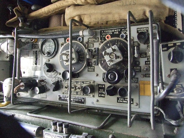
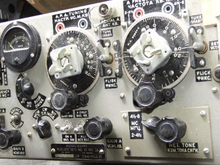
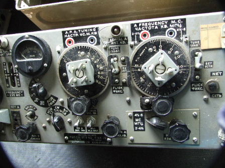
control on the Mk III only and slightly different switching of the intercom facility between the Mk's. The aerial is matched to the set using a
Variometer, or roller coaster, a round can like object with a scale that rotates beneath a small window.
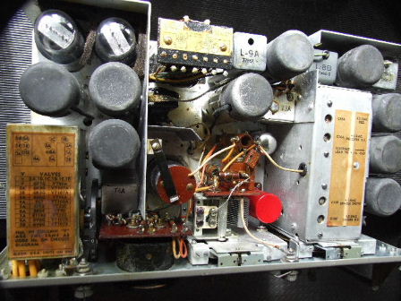
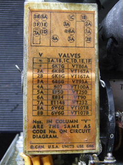
The set utilises 9 valves in the HF "A" set and 6 in the vhf "B" set. The output valve in the "A" set is the famous 807, AM is achieved by low level
grid modulation of the output valve. One interesting application is V3, this double diode pentode operates as the audio detector and avc, the rx audio
output stage, the tx mic amplifier and as the audio oscillator for MCW.
As used in the field, the "A" set operated into a 12 ft whip aerial on the back of the tank with the "Roller Coaster" aerial tuning unit in line,
whilst the "B" set was designed to feed a 20 inch rod aerial direct. Communication range was supposed to be about 10 mile hf r/t, 20 mile HF CW and
half a mile for the VHF signal.
A complete 19 set installation is quite large. There are many control box's, junction box's, aerial arrangements, leads and the like that could all be
used in numerous combinations that made the set very versatile in its use. The set even had the facility of being patched into the infantry network
via the 38 set and suitable connectors and control boxes.
Though many 19 sets can be found today, getting one working is not always easy. In the Mk III power supply, the high tension voltage for the receiver
comes from a vibrator, the transmitter ht from a rotary generator. The usual problem is that the vibrator has packed up and you cannot get the receiver
ht volts.
There are two ways to deal with this, one is to cut the vibrator case open, about 1 inch up from the bottom, then to try and clean the contacts
inside. This sometimes works, sometimes not. The other way is to replace the vib with a transistor equivalent, quite easy when you know how. If fact,
I have replaced all my vib's with just such devices.
Restoration
For those collectors and re-enactors who have the amateur radio licence then the sets can be restored, got working and used. Though it would be
theoretically possible to get the set going on the CB frequencies it would still not be possible to use the set as it is not "type approved". If a
set was acquired with the VHF section removed, a very common occurrence these days, then a small legal CB set could be fitted inside and this used instead.
Most of the capacitors within the set are of the wax variety. 30 to 40 odd years of hibernation and the sudden application of the searing voltages can
prompt several to raise the white flag and die. Luckily there may be no bangs, just a sizzling sound and great globules of melted wax over the work bench.
With several of the wax jobs removed and modern replacements fitted, I can hear the purists groaning from here, the set can again be tried out. In fact,
there are purists who would cut open the old capacitor, remove the innards and replace them with modern types, the old case would then be closed and
re-fitted into the set. Unfortunately, I am far too lazy, so new capacitors go straight into any set I am restoring.
A common fault on these sets, and others of the time, was that the audio output transformer primary would go open circuit, it then needs replacing.
The BFO (Beat Frequency Oscillator), used for CW reception, can cause problems though. Due to the way the set operates on transmit the BFO has
to be working. On receive it is a normal single conversion superhet, with BFO injection and diode detection. On transmit however, the BFO signal
is now mixed with the receiver local oscillator, which is left running all the time, to give a signal back at the aerial frequency, this is then
amplified and passed to the pa stage. So, if the BFO does not work, whilst not being able to receive CW or SSB signals, you have no tx signal either.
Initially there may be a lot of jumpiness about the tx signal, for those of you who can legally use the set, obviously the years of idleness
does little to enhance the screening and screws, the earthing and shields. The corrosion or oxidisation work's its magic into the earth connections
and screws etc so that there are lots of new earth paths for the tx to work on. Again, after a short while, the main decoupling capacitor for the
pa stage can give up the ghost and also die. The trouble there is in finding suitable high voltage capacitors these days. Much searching in junk box's
should find a suitable replacement.
One other consideration was to do with the microphone, originally a dynamic type, one example I had refused to work though. As I had plenty of carbon
microphones, No3, one of them was pressed into service. Taking a voltage feed off the heater rail, via a variable resistor, the mic was wired in series
with the original mic transformer primary. More than enough audio was available, varying the potentiometer altered the microphone output and was adjusted
for best audio.
On the air at last
A recent restoration set was finally ready for testing on the air. Using a commercial amateur tuning unit the set gave a good 8 watts into the aerial,
with good depth of modulation. Almost immediately, contacts were made on the 80 Mtr amateur band with stations in York (130 mile away) and South Wales
(100 mile away), both stations also using 19 sets, good reports were exchanged between all stations.
After a further tune up, with the set at the lowest end on the band the trimmers were peaked, returning to 80 Mtrs gave a 10 watt output now.
An amount of FM was present on the transmit carrier on modulation peaks. Careful selection of the oscillator valve, the 6K8G, reduces this effect
but additional filtering to the receive supply voltage was also added just to give extra help in curing the problem. A voltage stabiliser could be
added to the set and the local oscillator and BFO ht supplied from that.
The High Power Amplifier, No 2
There is a matching amplifier that will boost the output of the WS 19 to around 20 to 30 watt. There are two versions, one using four 807 valves in
parallel and one using two 807 valves in parallel. A rotary generator inside provides the ht voltage, along with several relays and the output
tuned circuits. The amplifiers operate in a linear mode, as AM is being fed into it, though a switch is provided on the front panel to allow for
CW operation and the altering of the bias arrangements. It should be noted that the aerial tuner for the amplifier is different from the 19 set one.
As stated before, the complete WS 19 had many different control box's allowing the set to be used in tanks, the back of jeeps, even as base
stations with a connection to the fieldphone systems. Many different interconnecting cables, plug and socket arrangements were issued, collecting
all the additional bits to the system should keep you going for years to come. If I can help with circuits or modification details then please
get in touch with me.
Do get in touch if you have any military sets to dispose of, I can collect or am willing to pay postage etc, whichever is the easiest. Even if I have a nice example already in the collection I may still know of someone else who is looking for such. It all helps in this often difficult world of collecting.
Send an e-mail to: Ben Nock, G4BXD
(If link does not work on your PC then send email to: [email protected] )
********* Pictures by G4BXD are G4BXD copyright ********
|
|
|
|
|
|
|
|
|
|
|
|
|
|
|
|
|
|
|
|
normal green colour |
unusual blue colour. Navy ? |
19 or 22 set use |
|
|
|
|
internal photo with key, fuses & bulbs |
Box No3 |
dyno/vib version |
One item often at fault is the Headset/mic combination. This is the twin padded headset with microphone No4 etc combined into a single drop lead with the 5 pin rubber plug on the end. The usual fault is that the small loudspaker coils in the headset go open circuit. There is enough space inside them though to replace the old coil with a modern loudspeaker or insert.
Recently I found another headset with duff phones. Pictures show the replacing of phones with small speakers.
There is a small ball bearing lodged in the thread of the front cover and the speaker housing. I could find no way of removing other than drilling it out. The first pic shows the resulting hole. With the ball bearing popped out the front disk unscrews from the body part.
The Wireless Set No19
by
Ben Nock
In these past few years of World War Two remembrances, many thoughts about radios and how they were fitted to vehicles and used in campaigns have arisen. Many collectors and Radio Amateur operators have, over the years, brought new life to many war time sets, those that covered any licensed amateur frequencies are indeed capable of being fired up in anger once again and actual contacts made on the air.
My own interest in vintage equipment started some 30 years ago with the acquisition of a WS No 19 and an R1155 RAF receiver. Over the years I have restored many sets and, where possible, have used my amateur radio licence to fire them up on an amateur band and make many interesting contacts. It is always a good talking point to mention that the QSO (shorthand term for a radio contact) is being made with what is now a 50 or 60 year old piece of equipment.
The WS 19 was probably one of the most famous sets of the second world war, used in all theatres where the British were involved, in tanks, jeeps, on the back of pack animals, up mountains and in deserts. The 19 set was in fact still in use many years after the war, though in later years as a training set, I even have an example with a REME (Royal Electrical & Mechanical Engineers) workshop stamp on it dated as late as 1962. This was the date it was last refurbished at the workshops.
The 19 set was one of the mainstays of British Army communications throughout the second world war, three versions being produced, the MK I, II and III. The sets covered 2.5 to 6.25 Mhz in the Mk I, and 2 to 8 Mhz in the Mk II and III in two bands, capable of AM (Amplitude Modulation) , MCW (Modulated Morse Code) and CW (Morse Code) operation. The set in fact contained two systems, the HF system and a VHF unit running on around 230 Mhz with what is termed a regenerative receiver and AM transmitter.
The HF set was supposed to run around 12 watt, or 30 watts of rf with an external matching linear amplifier, see photograph, and the built-in VHF set around 3 watt, though now, with ageing components, the HF output can be a lot less than the manual states. It is not wise to try and fire up the old VHF section, this now lies within the military aircraft band, and they will not like any odd squawks etc up there.
The 19 set has an external power supply unit, the Mk I supply running one dynamotor and the Mk II utilising two motors and a Mk III with one rotary and a vibrator, running of 12 volt dc, they produced 275 on receive and 500 volt dc on transmit. Other differences between the Mk's included an RF gain control on the Mk III only and slightly different switching of the intercom facility between the Mk's. The aerial is matched to the set using a Variometer, or roller coaster, a round can like object with a scale that rotates beneath a small window.
The set utilises 9 valves in the HF "A" set and 6 in the vhf "B" set. The output valve in the "A" set is the famous 807, AM is achieved by low level grid modulation of the output valve. One interesting application is V3, this double diode pentode operates as the audio detector and avc, the rx audio output stage, the tx mic amplifier and as the audio oscillator for MCW.
As used in the field, the "A" set operated into a 12 ft whip aerial on the back of the tank with the "Roller Coaster" aerial tuning unit in line, whilst the "B" set was designed to feed a 20 inch rod aerial direct. Communication range was supposed to be about 10 mile hf r/t, 20 mile HF CW and half a mile for the VHF signal.
A complete 19 set installation is quite large. There are many control box's, junction box's, aerial arrangements, leads and the like that could all be used in numerous combinations that made the set very versatile in its use. The set even had the facility of being patched into the infantry network via the 38 set and suitable connectors and control boxes.
Though many 19 sets can be found today, getting one working is not always easy. In the Mk III power supply, the high tension voltage for the receiver comes from a vibrator, the transmitter ht from a rotary generator. The usual problem is that the vibrator has packed up and you cannot get the receiver ht volts.
There are two ways to deal with this, one is to cut the vibrator case open, about 1 inch up from the bottom, then to try and clean the contacts inside. This sometimes works, sometimes not. The other way is to replace the vib with a transistor equivalent, quite easy when you know how. If fact, I have replaced all my vib's with just such devices.
Restoration
For those collectors and re-enactors who have the amateur radio licence then the sets can be restored, got working and used. Though it would be theoretically possible to get the set going on the CB frequencies it would still not be possible to use the set as it is not "type approved". If a set was acquired with the VHF section removed, a very common occurrence these days, then a small legal CB set could be fitted inside and this used instead.
Most of the capacitors within the set are of the wax variety. 30 to 40 odd years of hibernation and the sudden application of the searing voltages can prompt several to raise the white flag and die. Luckily there may be no bangs, just a sizzling sound and great globules of melted wax over the work bench.
With several of the wax jobs removed and modern replacements fitted, I can hear the purists groaning from here, the set can again be tried out. In fact, there are purists who would cut open the old capacitor, remove the innards and replace them with modern types, the old case would then be closed and re-fitted into the set. Unfortunately, I am far too lazy, so new capacitors go straight into any set I am restoring.
A common fault on these sets, and others of the time, was that the audio output transformer primary would go open circuit, it then needs replacing. The BFO (Beat Frequency Oscillator), used for CW reception, can cause problems though. Due to the way the set operates on transmit the BFO has to be working. On receive it is a normal single conversion superhet, with BFO injection and diode detection. On transmit however, the BFO signal is now mixed with the receiver local oscillator, which is left running all the time, to give a signal back at the aerial frequency, this is then amplified and passed to the pa stage. So, if the BFO does not work, whilst not being able to receive CW or SSB signals, you have no tx signal either.
Initially there may be a lot of jumpiness about the tx signal, for those of you who can legally use the set, obviously the years of idleness does little to enhance the screening and screws, the earthing and shields. The corrosion or oxidisation work's its magic into the earth connections and screws etc so that there are lots of new earth paths for the tx to work on. Again, after a short while, the main decoupling capacitor for the pa stage can give up the ghost and also die. The trouble there is in finding suitable high voltage capacitors these days. Much searching in junk box's should find a suitable replacement.
One other consideration was to do with the microphone, originally a dynamic type, one example I had refused to work though. As I had plenty of carbon microphones, No3, one of them was pressed into service. Taking a voltage feed off the heater rail, via a variable resistor, the mic was wired in series with the original mic transformer primary. More than enough audio was available, varying the potentiometer altered the microphone output and was adjusted for best audio.
On the air at last
A recent restoration set was finally ready for testing on the air. Using a commercial amateur tuning unit the set gave a good 8 watts into the aerial, with good depth of modulation. Almost immediately, contacts were made on the 80 Mtr amateur band with stations in York (130 mile away) and South Wales (100 mile away), both stations also using 19 sets, good reports were exchanged between all stations.
After a further tune up, with the set at the lowest end on the band the trimmers were peaked, returning to 80 Mtrs gave a 10 watt output now. An amount of FM was present on the transmit carrier on modulation peaks. Careful selection of the oscillator valve, the 6K8G, reduces this effect but additional filtering to the receive supply voltage was also added just to give extra help in curing the problem. A voltage stabiliser could be added to the set and the local oscillator and BFO ht supplied from that.
The High Power Amplifier, No 2
There is a matching amplifier that will boost the output of the WS 19 to around 20 to 30 watt. There are two versions, one using four 807 valves in parallel and one using two 807 valves in parallel. A rotary generator inside provides the ht voltage, along with several relays and the output tuned circuits. The amplifiers operate in a linear mode, as AM is being fed into it, though a switch is provided on the front panel to allow for CW operation and the altering of the bias arrangements. It should be noted that the aerial tuner for the amplifier is different from the 19 set one.
As stated before, the complete WS 19 had many different control box's allowing the set to be used in tanks, the back of jeeps, even as base stations with a connection to the fieldphone systems. Many different interconnecting cables, plug and socket arrangements were issued, collecting all the additional bits to the system should keep you going for years to come. If I can help with circuits or modification details then please get in touch with me.
Send an e-mail to: Ben Nock, G4BXD
(If link does not work on your PC then send email to: [email protected] )
********* Pictures by G4BXD are G4BXD copyright ********