1.3GHz SSPA and Controller
I have used a valve PA with 4 x 2C39A for about 30 years now, it has been rather temperamental recently and the tuning drifts a lot. When W6PQL made kits available for XRF286S based amplifiers I decided to use them to build a new SSPA to replace the old valve amp. I had a suitable heatsink and 28V 50A power supply. Finding the time to build the amp had to wait until I had retired and finished building a workshop where I could complete the metalwork needed.
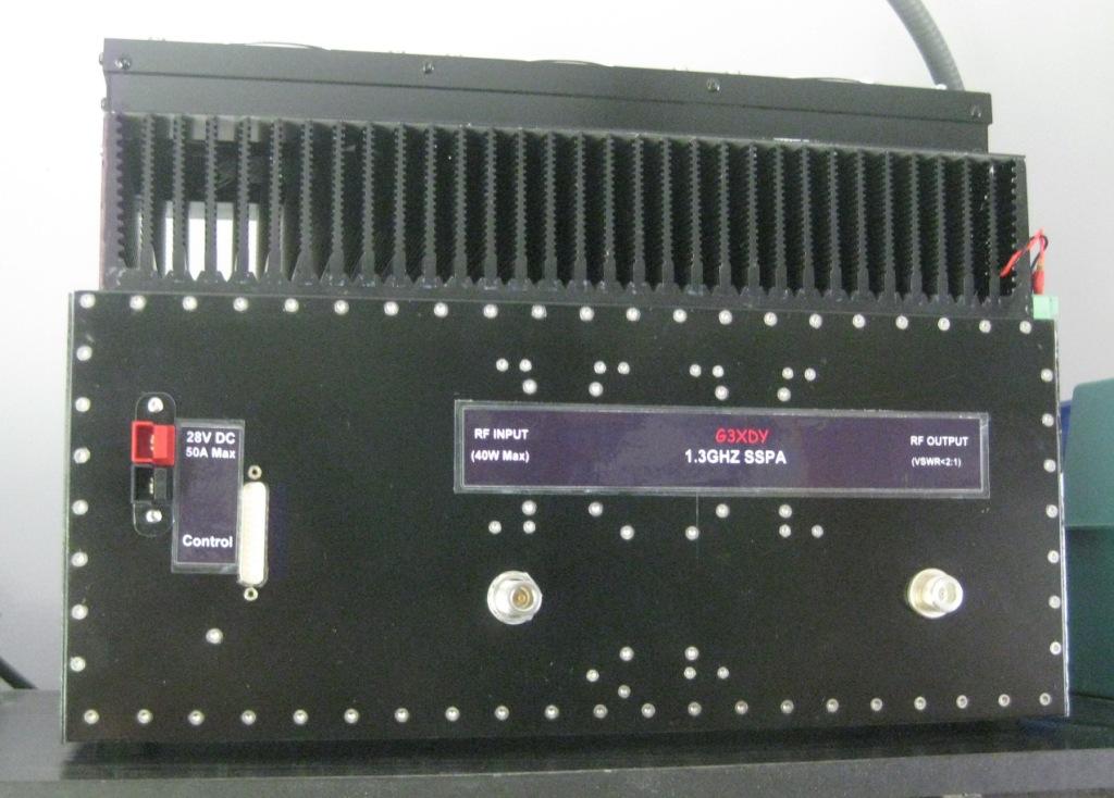
With my current transverter the drive power available limits maximum output to about 500W PEP. The PA includes a harmonic filter to notch out the 2nd, 3rd and 4th harmonics, and a reflectometer to measure output and VSWR.
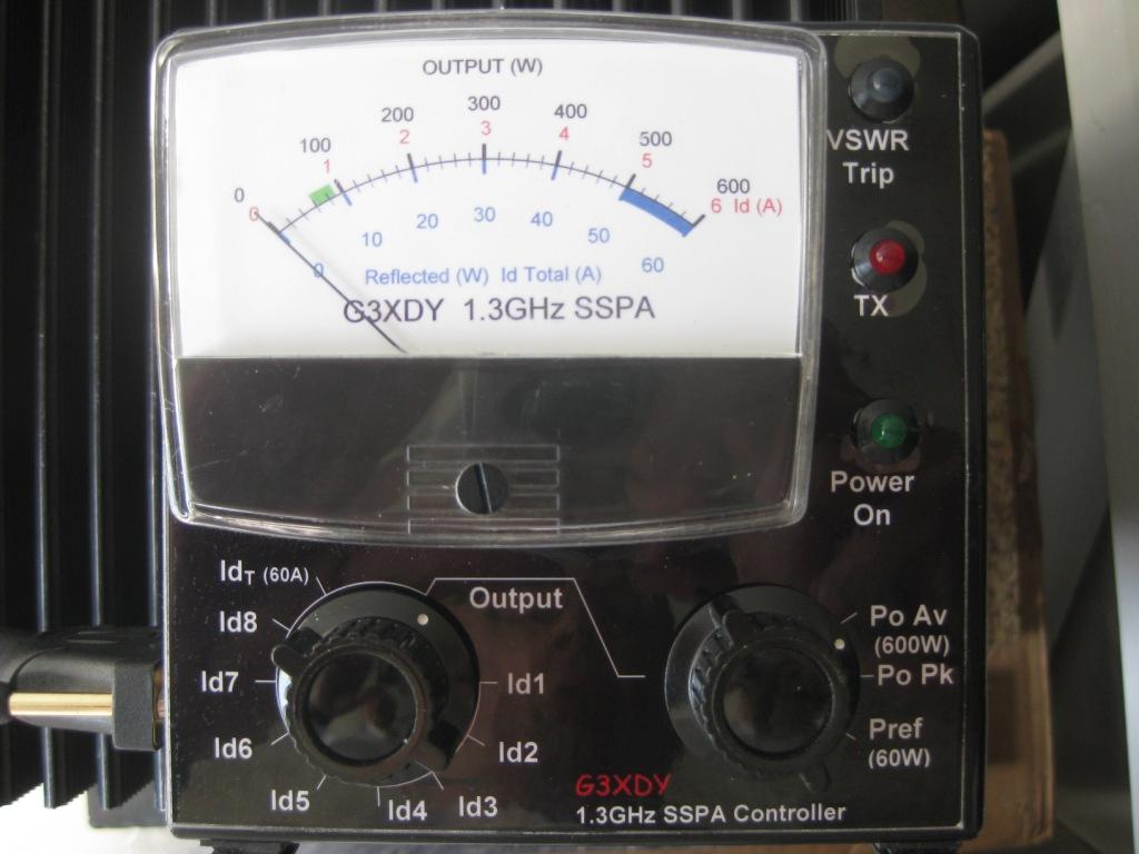
The control circuits are remote from the PA, and provide metering of drain currents, plus forward and reverse power. Forward power can be displayed as peak or average power. The controller uses a PIC 16F873A to measure the forward and reflected power through A/D converters, then display the power on a linear scale meter through a look-up table feeding into the PWM output from the PIC. If the reflected power exceeds 50W a comparator is tripped and an interrupt routine will close down the PA within a few microseconds. The controller also interlocks the 2.3GHz system which shares the same feeder so that only one system can transmit at once. Finally, there is a temperature sensor on the PA heatsink that operates the cooling fans. The fans start up at half power at just over 30 deg C, and reach full speed at about 62 deg, using a low frequency pulse width modulation scheme.
See photos here: