3400MHz System
Upgrade
Introduction
The new 432MHz transverter described elsewhere includes
facilities for improved control of the 3.4GHz system, but this needed some
modifications to the masthead system which have now been completed. The new
system now switches the LO injection off in the transverter when the band is
not selected, and a second isolation relay disconnects the antenna from the
receiver and terminates the receiver input in 50 ohms. This will permit the use
of a dual band 13/9cm feed without having to worry about isolation issues. The
LO circuit in the transverter has been modified to accept an external LO signal
and the crystal re-used in the new LO, using the DF9IC PLVCXO design to lock
the frequency to the 10MHz reference which is diplexed
with the 432MHz IF on a single coax. A 10MHz output is available from the
masthead system, to lock the 5.7GHz and 10GHz systems in due course.
PLVCXO
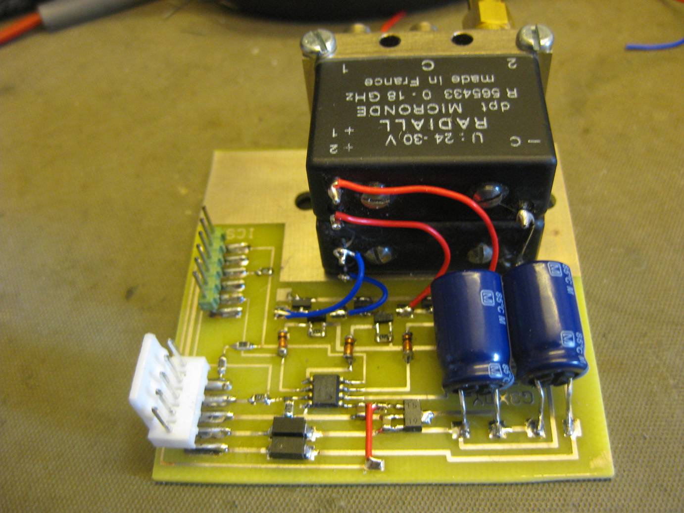
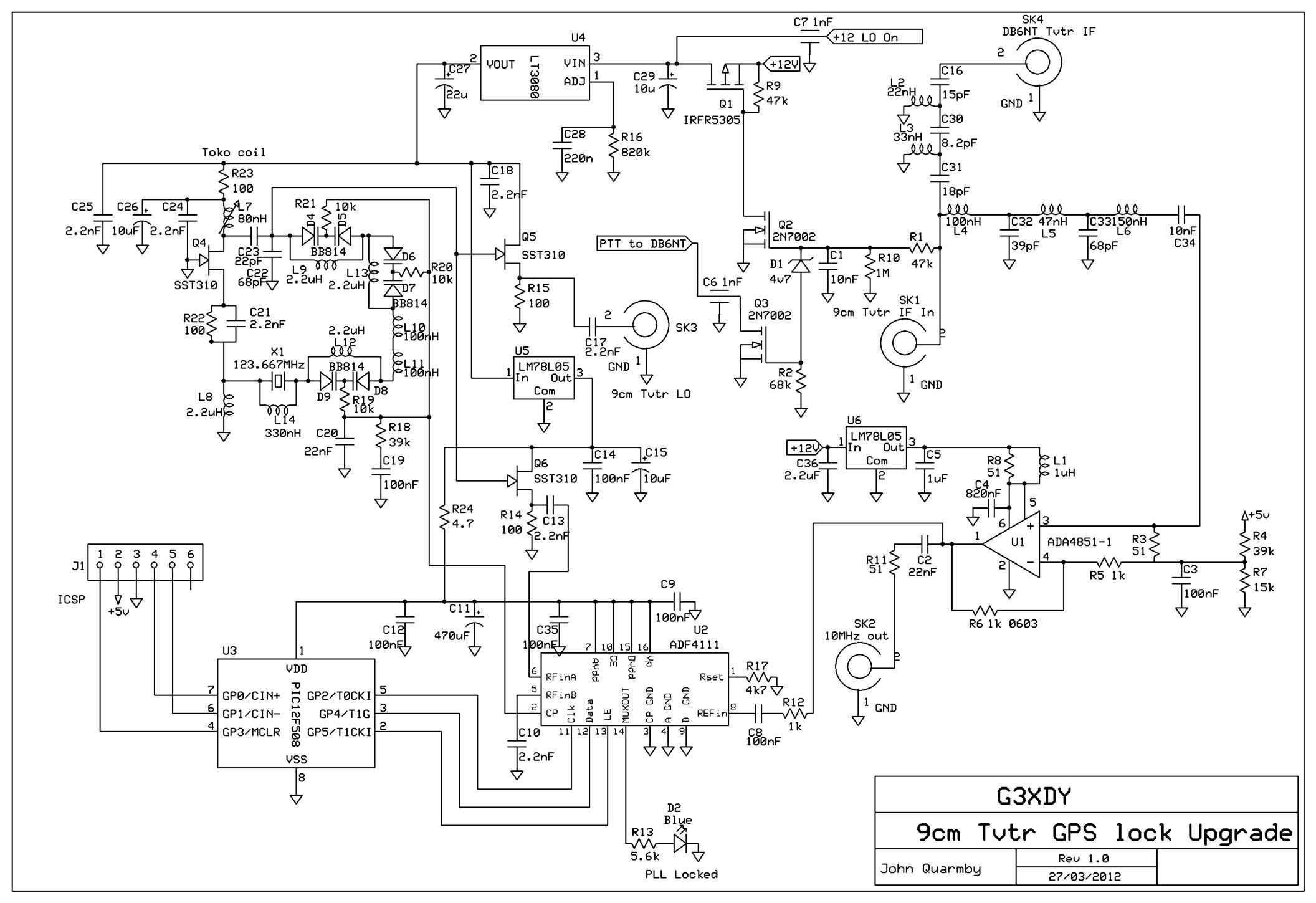
The DF9IC PLVCXO uses a JFET (SST310) oscillator and buffers with three series connected dual varicaps to adjust the frequency. This circuit arrangement offers a good pulling range and nearly linear frequency change versus control voltage. The PLL is an Analogue Devices ADF4111 (more readily available at the time than the ADF4110 specified in the original article). This is controlled using a 12F508 PIC which loads the PLL registers 100mS after power is applied. The VCXO operates on 123.6666667MHz to give a final LO frequency of 2968.000000MHz. The VCXO frequency is divided down and compared with a 333.3333kHz signal derived from the 10MHz reference. The PLVCXO output is connected via a 100pF capacitor to the point in the DB6NT transverter where the crystal was previously connected.
Control Circuits
The masthead module also includes the diplexer for the 432MHz IF and the 10MHz reference signals. The coax also transports a DC signal from the 432MHz transverter. With no DC applied the PLVCXO is off and the twin antenna relays are set to isolate the 9cm transmitter and receiver from the antenna. When 5V is applied to the coax, the PLVCXO is switched on, and the receive isolation relay changes over to connect the RX to the antenna. When the voltage increases to12V the system goes to transmit, isolating the receiver and connecting the TX to the antenna. This is all controlled by MOSFET switches. An AD4851-1 wideband op-amp is used to amplify the 10MHz reference signal by 6dB to counteract any cable losses and square up the waveform, this feeds the PLL and the 10MHz output socket.
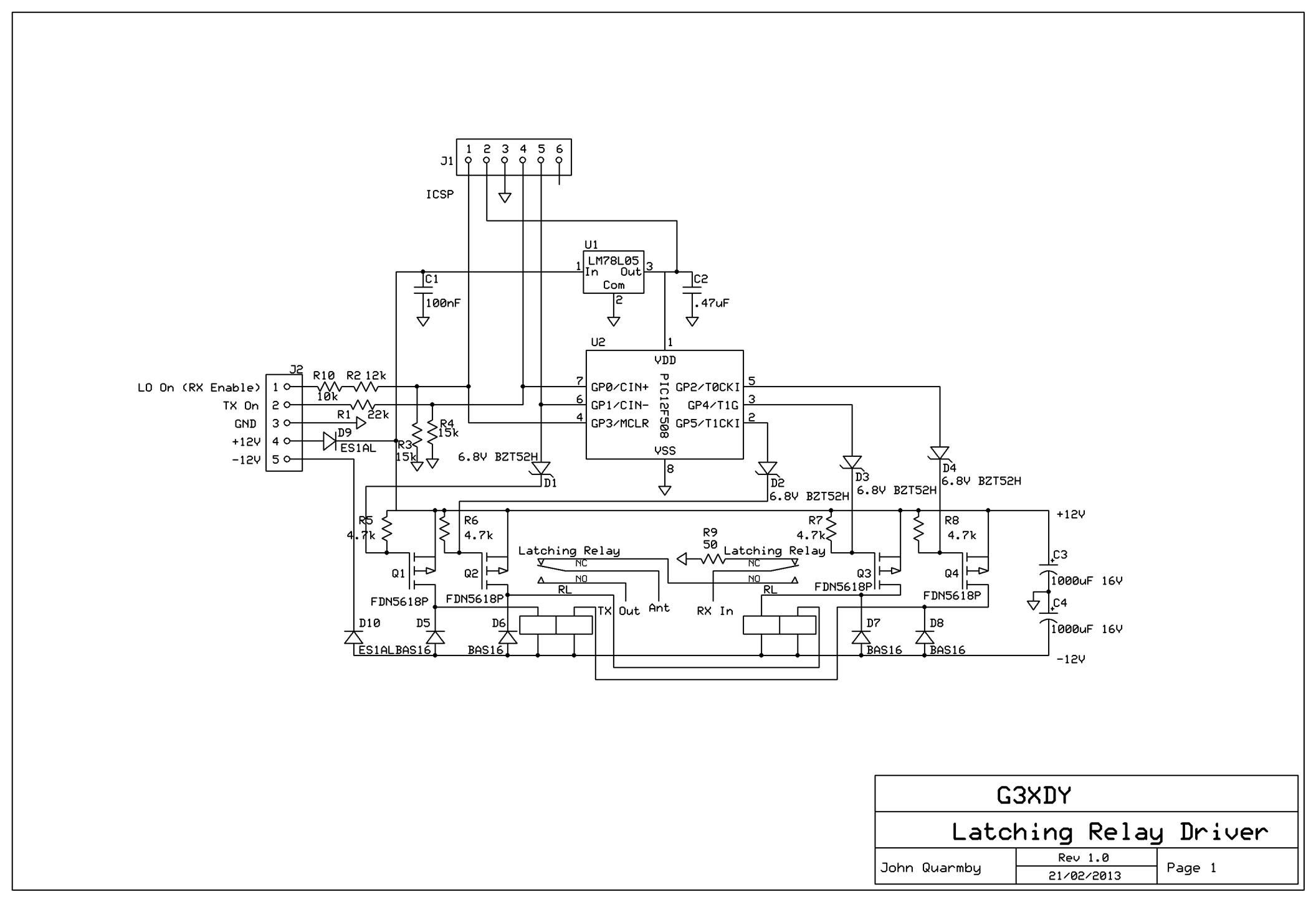
Relay Control
The two relays used in this transverter are latching types using two coils with a common negative terminal. A 12F508 PIC based controller has been designed to provide 100mS operate pulses to the relays and full interlocking and safety features. This includes the ability to reset to a safe condition if the power fails for any reason. The relays are powered from +12V and -12V rails already available in the masthead system, using level shifting zener diodes to drive the MOSFET switches controlling each relay coil.