K2 Project
(Last updated on 3rd January 2008)
 One of my favourite radio interests is CW contesting and I operate in many of the European contests,
usually in a QRP category. Currently, my shack is confined to a corner of the living room which limits the
size and quantity of equipment that I can use.
To fit the available space, I have been using an Icom IC706mkIIG, which was originally my mobile rig. Whilst this is a compact, flexible rig,
the performance on the LF bands at night is quite poor compared to my IC735. Considering that the current point
in the sunspot cycle means that the LF bands will be the most useful bands for the next 3-4 years,
I realized that I needed to upgrade my station to operate effectively on the lower bands.
One of my favourite radio interests is CW contesting and I operate in many of the European contests,
usually in a QRP category. Currently, my shack is confined to a corner of the living room which limits the
size and quantity of equipment that I can use.
To fit the available space, I have been using an Icom IC706mkIIG, which was originally my mobile rig. Whilst this is a compact, flexible rig,
the performance on the LF bands at night is quite poor compared to my IC735. Considering that the current point
in the sunspot cycle means that the LF bands will be the most useful bands for the next 3-4 years,
I realized that I needed to upgrade my station to operate effectively on the lower bands.
After reading many positive reviews of the Elecraft K2, it seemed this was the ideal compact CW rig and I decided to purchase a kit.
Various contesters and DXpeditioners were impressed with the K2's performance and I liked the fact that the K2 is primarily a CW rig, with SSB as an option.
Most Japanese rigs are SSB radios with CW added as an afterthought, so have poor QSK performance, many still using relays instead of solid state T/R switches.
In March 2005, I went to the USA on a 3 week business trip, so ordered a K2 kit with Noise Blanker and 160 metres
options and arranged for Elecraft to deliver it locally. I planned to work on kit assembly during some
evenings in my hotel room, so brought a few hand tools and borrowed a Weller soldering station from Willis, KB1JFG.
Using my hotel room as a makeshift workshop,I managed to complete the Control and Front Panel boards whilst there and also successfully
pass the Stage 1 testing and alignment. The hotel room had poor lighting, so I resorted to getting up at 5AM and checking my workmanship in daylight with the sun shining through the window.
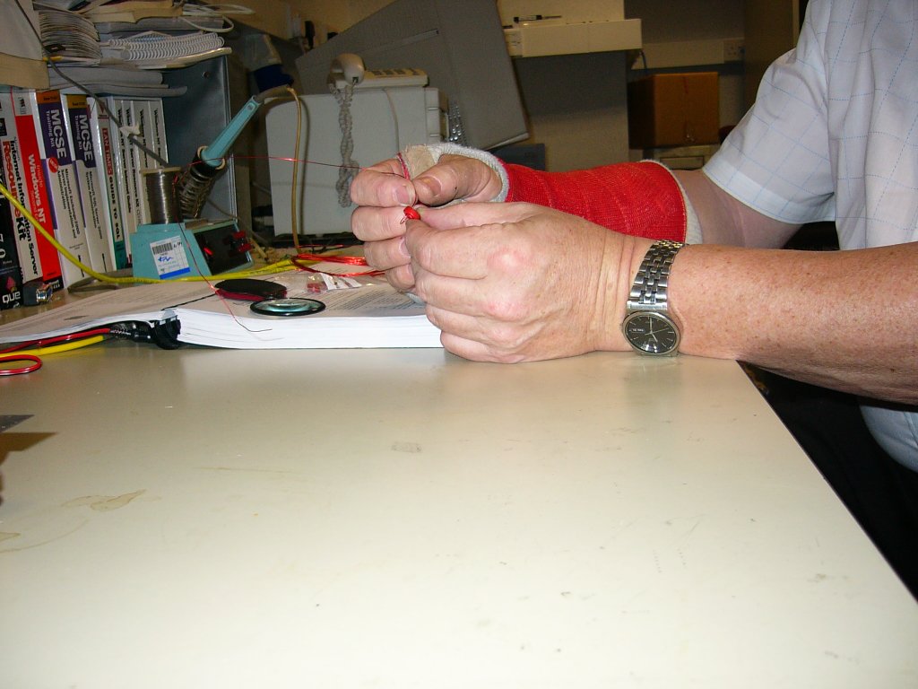
After this, I completed most of the Stage 2 assembly on the RF board, but was not able to wind the toroids, having fractured my wrist slipping and falling on an icy patch outside the W1SRG shack on the WPX SSB Contest weekend.
The project was originally put on hold for four weeks, when the cast was due to be removed from my arm. After a week of inactivity, I was getting severe "construction withdrawal" symptoms
and was impatient to see if the K2 would successfully complete the Part 2 testing , so I persevered at winding toroids with my clumsy right arm. Despite the handicaps I had been working under,
all the Part 2 testing was successful and I was delighted to hear 40m signals on the K2. The receiver sounded great, although a little deaf because the filters had only been roughly aligned to the values in the handbook.
After reading the construction steps to complete Part 3, I realized there was only less than a day's construction remaining.
Instead of being happy to be close to completion, I felt a little sad, because the actual kit construction is very enjoyable.
To console myself, I built the 160 metres and Noise Blanker options, then completed the K2 construction after winding more toroids.
On the Part 3 testing, as well as the receiver seeming somewhat deaf on 40 metres, the transmitter went into self-oscillation when adjusting the bandpass filters.
I did a quick search on the Elecraft reflector and found a few posts mentioning the xmit problem being due to the +8volts receive voltage and the T/R switch.
Sure enough, the +8R was at 1.85v instead of ground during transmit. The FETs on the logic board are the usual suspects, but mine were OK. After some debugging I traced the problem to Q23 on the RF Board,
which had a broken leg - possibly damaged while constructing the RF board, as it is located at the very front.
After replacing the FET, I was able to get about 14 watts output on 40 metres with no instability or overcurrents. Shortly after this success, the receiver went completely deaf on the next powerup. Using a noise generator, it seemed the post-mixer amplifier wasn't working.
An inspection revealed an unsoldered joint on the capacitor from Q22's collector to the resistive pad.
After soldering this joint, the receive path was fine, so I spent another 15 minutes re-examining all joints on the RF board for poor or missing solder, but all looks ok.
From the troubleshooting, I realized that the K2 receiver is exceptionally quiet unless there is a signal present from the antenna, which really impressed me.
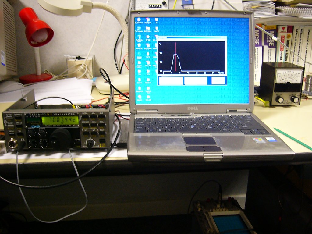
A full alignment was then undertaken, which was not too difficult. Using Spectrogram made alignment of the IF filter/BFO frequencies quite easy. The actual alignment plots can be seen here
The K2 was completed in mid-May 2005 and was first used in the CQ WPX CW Contest. The receiver performance was oustanding compared to the IC706mkIIG.
K2 Options
Another business trip to the USA in June resulted in the purchase of the KPA100 Amplifier kit. I completed building the amplifier at the end of July, but didn't have time to set up and test it until October.
The adjustments were simple and I managed to get 100 watts output on all bands, except 160m which caused the rig to overcurrent and switch itself off.
A quick visual inspection revealed I had not soldered 2 pins on one of the Low Pass Filter relays.
After remedying this error, it was reassuring to get 100w out on 160m also.
In October 2005, I ordered and built the KSB2 SSB option. This was a nice kit to build, but it only took just over half a day to complete. No problems were experienced and it seems to work fine on receive. Eventually, I will plug in a microphone and test it on SSB transmit.
I now have a rig that I'm proud to own and use, a very satisfying experience
The final additional option was a KAF2 audio filter, built in December 2005.
I had originally contemplated the DSP2 option, but as I already own a Timewave DSP-9X, chose the KAF2 instead.
I'm glad I did as this is a very worthwhile addition for CW operators.
I found it easiest to align the 2 bandpass sections by using Spectrogram.
Normally, I operate CW with the AF1 section permanently enabled and it produces a pleasant sound.
The Real Time Clock seems to be a fairly useless feature. It's not very accurate and it's also not too easy to set up the display.
I also purchased the XG-1 Signal Generator at the same time. I used this often during 2008 to reassure myself that the RX was still working
due to the bands being almost totally dead with the worst Sunspot minimum I've lived through.
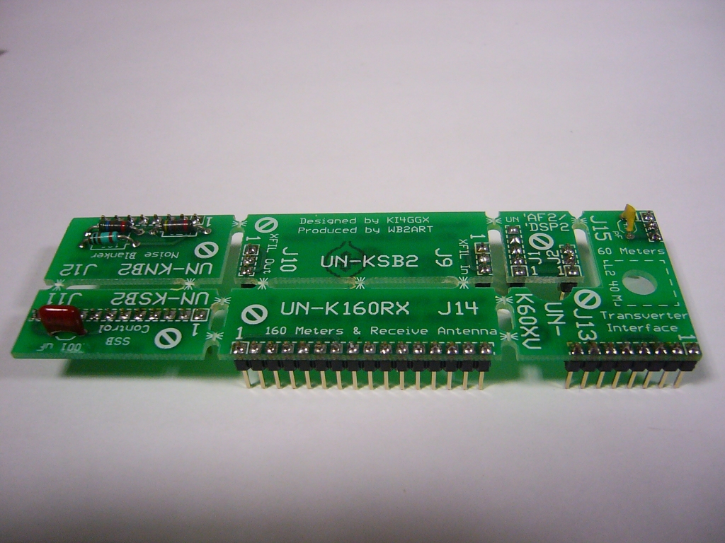
Now that my K2 had 4 option cards fitted, it also made sense to buy the Rework Eliminator kit from WB2ART.
This kit allows one to remove/replace option cards without any component removal/replacement or unsoldering/resoldering. The small pcbs are of similar fine quality to those used by Elecraft.
K2 Modifications
As can be seen in the later photos, I replaced the standard Elecraft tuning knob with a Yaesu FT100 knob. This is a popular modification and the knob with rubber ring can be bought direct from Yaesu as spare parts.
The relevant Yaesu part numbers are: RA006800B - Tuning Knob, RA0068200 - Rubber Ring. I don't know if these are still obtainable from Yaesu
I decided to add the capabilty of data modes to the K2, although I have no real idea why. In 2005, I made a total of 1385 QSOs, of which 1376 were on CW, 6 on RTTY, 2 on PSK and only one on SSB (to work a local club event), so this hardly justified even buying the KSB2 option.
Nevertheless, I built W3FPR's audio amplifier and mounted it on a standoff from the Logic Board. I also built a box to interface the K2 to a computer or possible microphone.
Implementing data modes on my K2 is still a work in progress and is quite low priority due to lack of sufficient enthusiasm.
The rig is a great QSK CW performer, and I no longer use any other modes.
A really worthwhile acquisition was a K6XX CW zero-beat indicator from WA3WSJ.
This is a SMD kit already assembled by Ed and cost just $35, including shipping.
To install it just requires connecting 4 wires to the front panel and it will illuminate the rightmost segment on the S-Meter barcode display when exactly zero-beated with a signal.
I glued the assembled PCB to the Front Panel PCB with epoxy and adjusted the tiny trimpot to peak at 700Hz. The led illuminated somewhat randomly, so I installed a 51K resistor in series with the AF input to the PCB and now it works well, enabling me to net precisely.
It's a pity that many people who call me seem to be unable to net.
After using the rig for just over a year since the last modifications were made, I was itching to take off the covers again. So in November 2007, I installed 2 small, but effective mods from G4BJM. One mod to the KAF2 increased AF gain and the other, to the Control Board, improved the QSK capability.
The next plan for my K2 is to experiment with a Softrock SDR as an outboard Q5'er. This involves adding a buffer amplifier to the IF chain and could come in useful when the sunspots return and the HF bands become busier.
In June 2009, I made a very effective modification relating to the K2's SSB implementation.
I have been inactive on the bands since 2016 and have not really worked up sufficient interest to continue with the hobby since. So in June 2020, I decided I no longer needed the K2 and sold it to Jon GW4LJW.
Hopefully this classic rig will provide him with as much enjoyment as it did me.
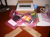
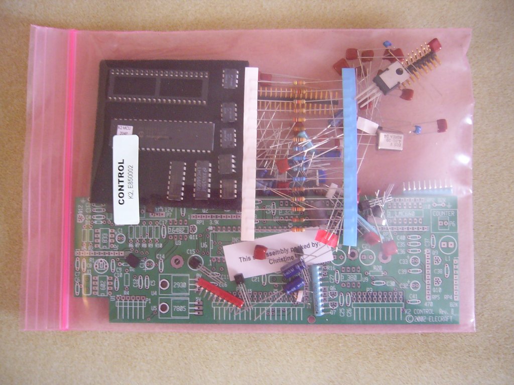
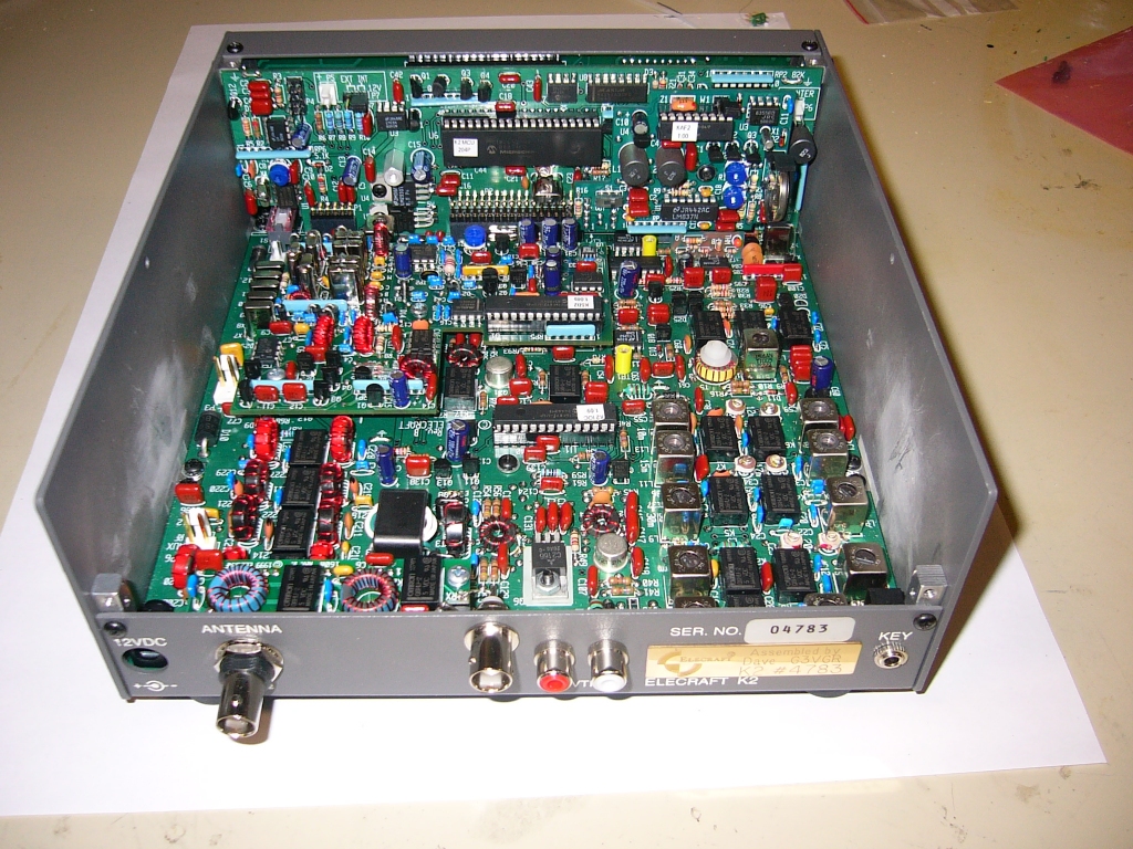
The opened kit, nicely put together and labelled |
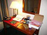
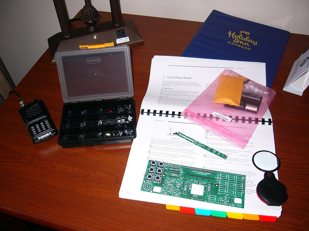
My hotel room workshop |

The kit of parts for the control board |
The Control Board almost completed. Total assembly time was around 4 hours |

After the Control board passed all the resistance tests, it was time to start on the Front Panel Board |
The Front Panel is almost complete, just the encoder to install. Total assembly time was around 3 hours |
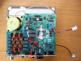
Part 1 Construction completed, the Control, Front Panel and RF board mate together well. The rig is starting to take shape nicely |
Rear view of the Part1 stage. Enough components on the RF board are present for testing of the Control and Front Panel boards |
The K2 passes Part 1 tests at the W1SRG shack. Seeing the self-tests pass and "Elecraft" show on the display gave me a great feeling of confidence |

Winding T37 toroids is a little tricky with my arm in a cast, but I managed somehow and was able to complete part 2 of the project with no mishaps |
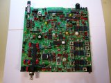
Part2 has been completed. The rig has just run PLL Cal. The RX seems a bit deaf, but I'll sort that out when the rig's completed
|
Part 3 also completed. No components left to solder in, which is a good sign. Now to fully inspect the soldering work, where I found a few unsoldered joints
|
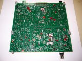
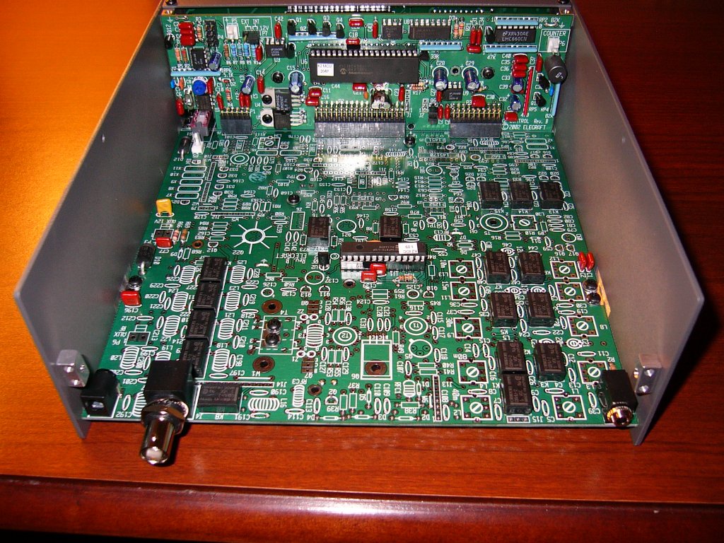
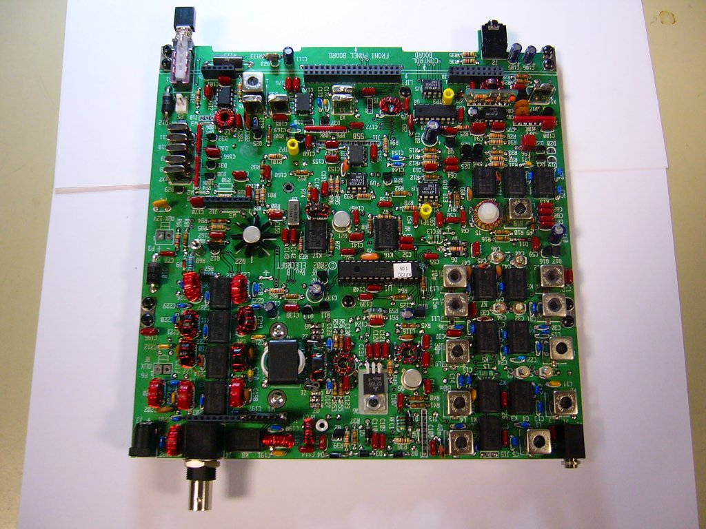
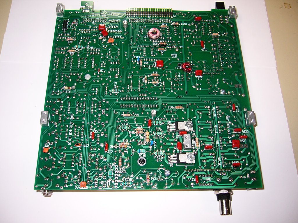
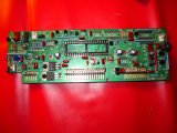
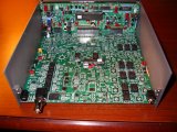
There're also a few more components fitted on the underside of the RF board. The 2 PA transistors can be seen at the front of the picture.
|
The built-in DMM is being used to check the VCO voltages on all bands as part of the alignment procedures |

Using Spectrogram and a homebrew Noise Source makes setting up the BFO frequencies quite easy |

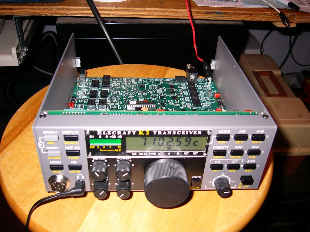
Aligning the bandpass filters on transmit. After fixing the TR switch, the transmitter is now stable on all bands |
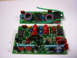
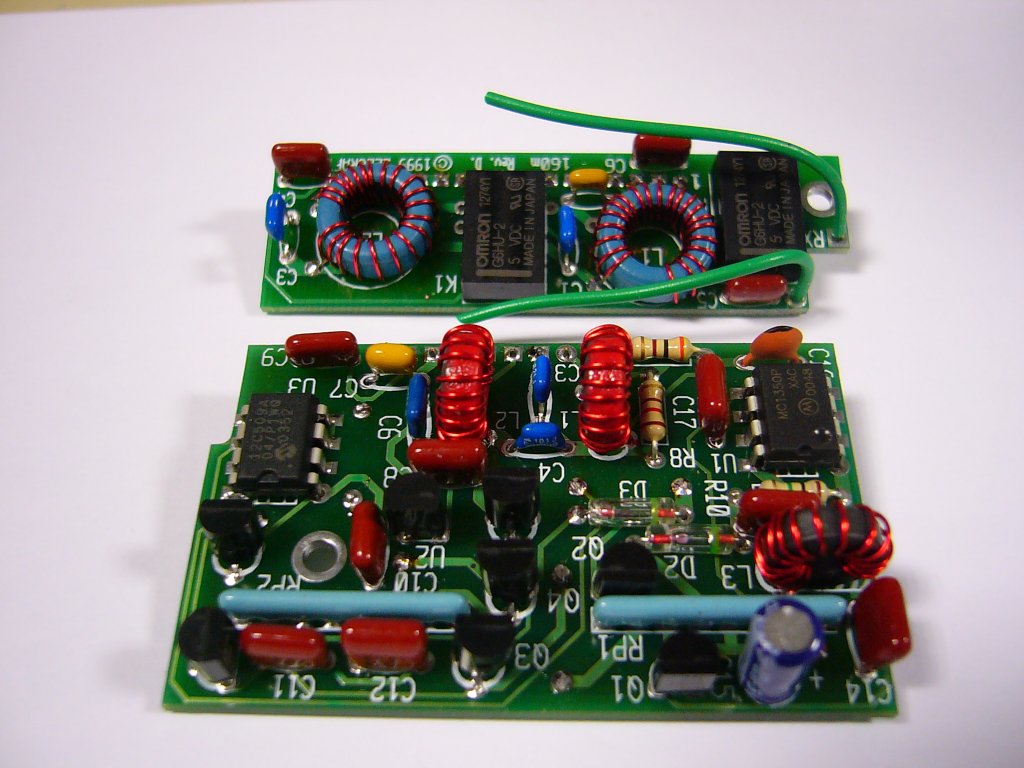
I've assembled both the 160m/RX Ant and Noise Blanker options ready for addition to the K2 |
The 2 option boards have now been installed in the completed K2. The next option will be the 100W PA |
The completed KPA100 Amplifier option ready to install in the K2. This was another nice kit to build |

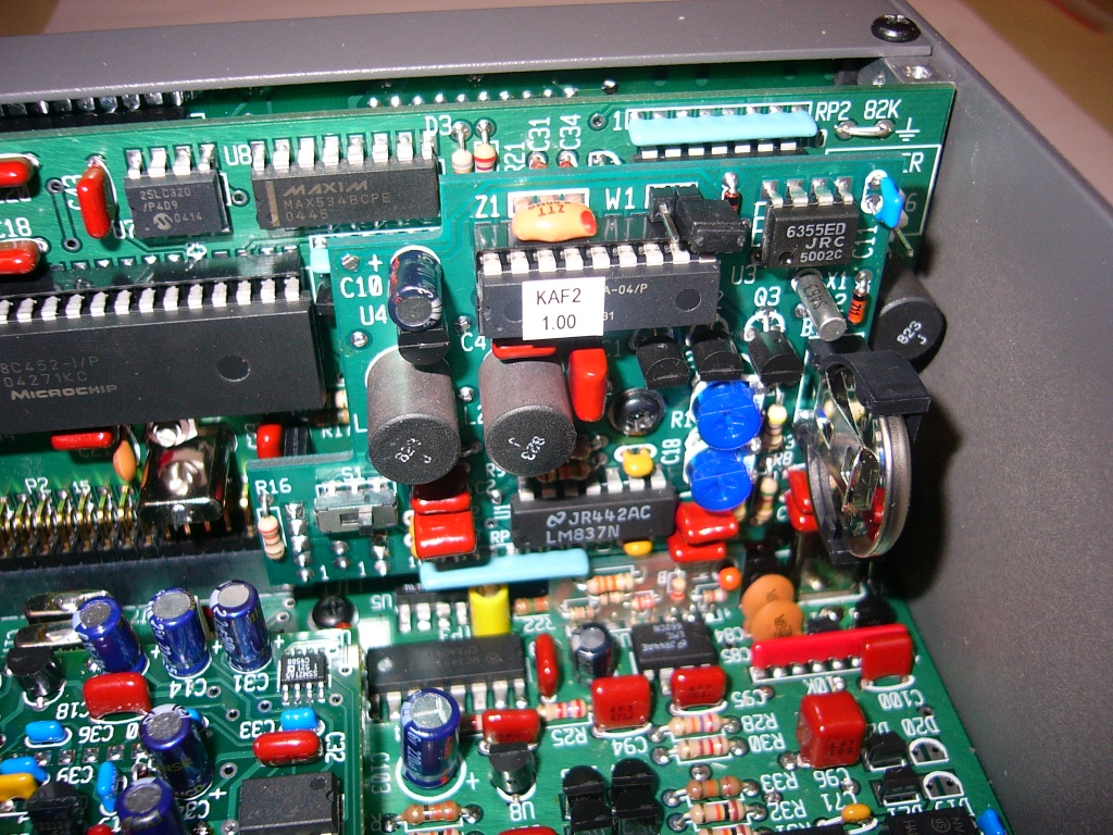
The KAF2 Audio Filter and Real Time clock is the last Elecraft option to be fitted to my K2 |

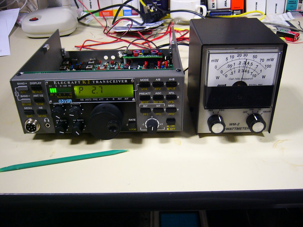
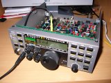
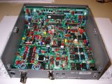
The K2 with the 4 options installed. The ID plate from WB2ART can be clearly seen |
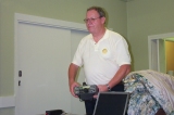
G3VGR giving a talk/demo of the K2 at LEFARS club |
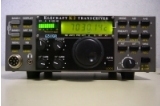
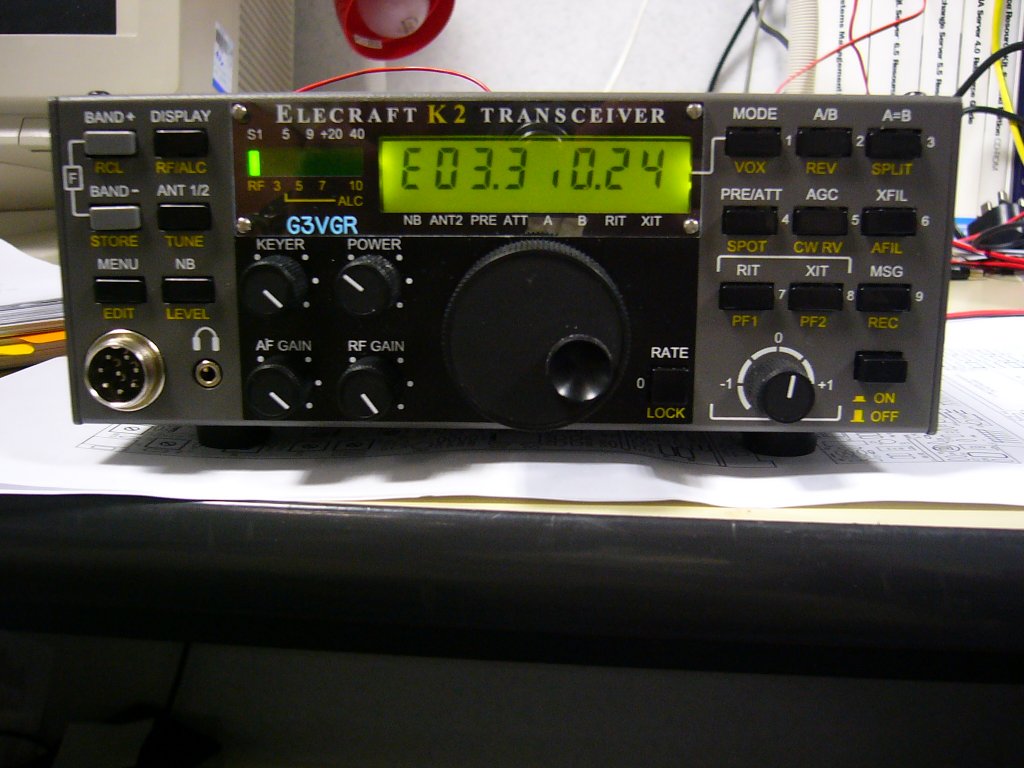
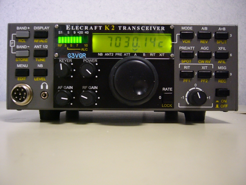
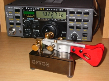
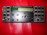
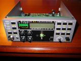
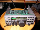
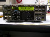
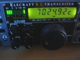
Front view of completed K2 #4783 (Dec. 2005) |
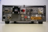
Rear view of completed K2 #4783 |

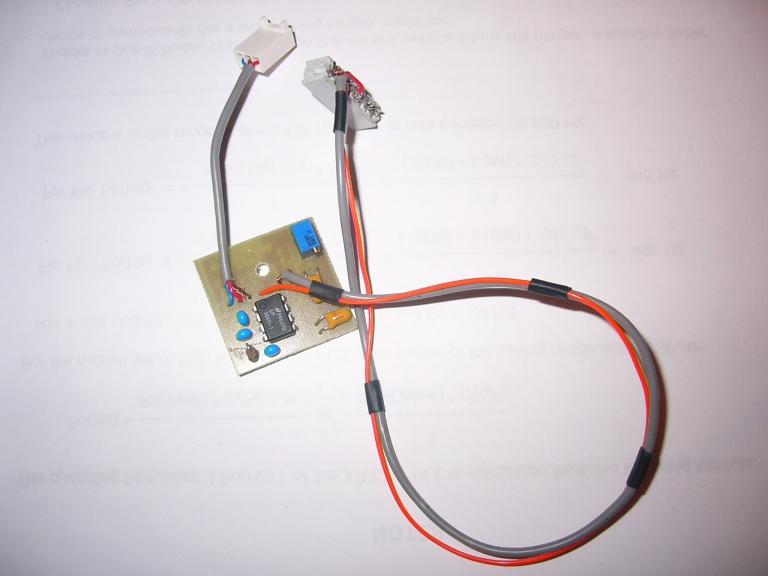
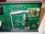
Original home-made AF Amplifier PCB. One lead is connected to J5 on the RF board and the other to the microphone header on the Front Panel |
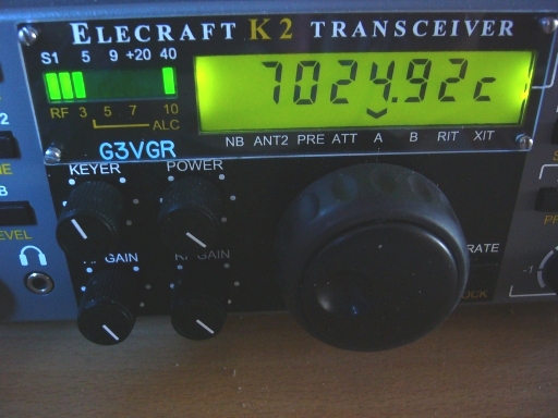
The compact K6XX tune indicator using Surface Mount components. The board is epoxied to the front panel PCB |
The rightmost bar lights when the received signal has been tuned to the same frequency as the sidetone |
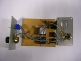
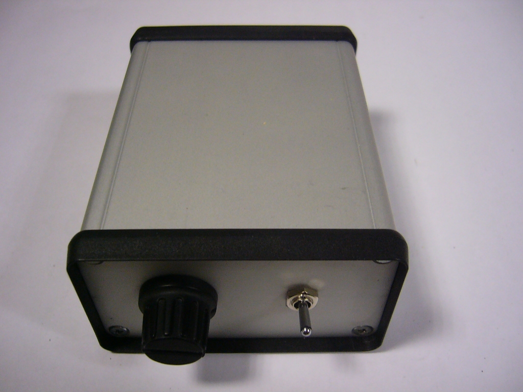
I built this box for use with digital modes. It switches between a soundcard and a microphone |
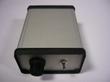
The completed datamodes box. It just needs painting and some labels applied.
|
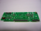
WB2ART's UNPCB rework eliminator modules before separating the individual boards
|
K2 Links
[Home]
 One of my favourite radio interests is CW contesting and I operate in many of the European contests,
usually in a QRP category. Currently, my shack is confined to a corner of the living room which limits the
size and quantity of equipment that I can use.
To fit the available space, I have been using an Icom IC706mkIIG, which was originally my mobile rig. Whilst this is a compact, flexible rig,
the performance on the LF bands at night is quite poor compared to my IC735. Considering that the current point
in the sunspot cycle means that the LF bands will be the most useful bands for the next 3-4 years,
I realized that I needed to upgrade my station to operate effectively on the lower bands.
One of my favourite radio interests is CW contesting and I operate in many of the European contests,
usually in a QRP category. Currently, my shack is confined to a corner of the living room which limits the
size and quantity of equipment that I can use.
To fit the available space, I have been using an Icom IC706mkIIG, which was originally my mobile rig. Whilst this is a compact, flexible rig,
the performance on the LF bands at night is quite poor compared to my IC735. Considering that the current point
in the sunspot cycle means that the LF bands will be the most useful bands for the next 3-4 years,
I realized that I needed to upgrade my station to operate effectively on the lower bands.