Valve Circuits (Battery) B4
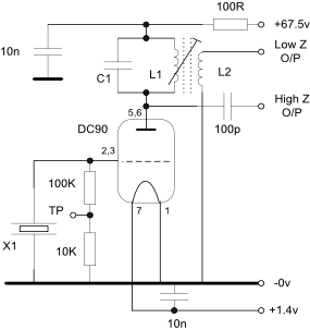
1. Tuned Anode Tuned Grid Oscillator
The DC90 was designed as a self oscillating mixer for 88-
If a series cut crystal is used the parallel resonant frequency will be several KHz or more higher than the series resonant frequency.
L1 should be adjusted just down the slow side from the peak of of the tuning characteristic for reliable starting. L1 / C1 should have a high L/C ratio.
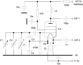
2. Colpitts Oscillator
This is a suggested circuit for a VFO for an HF receiver/transceiver and takes the form of a ‘high C’ Colpitts oscillator using a 1L4 or DF97.
Output 1 has a high impedance and output 2 has a much lower impedance -
A stabilised supply and some form of buffer to isolate the oscillator from the following stage(s) should be used for best frequency stability.
Test were conducted with a 1L4 with several different feedback capacitors and with C1 and C2 omitted and the results shown below. L2 had a 1K resistor temporarily wired in parallel to minimise circuit loading by the test equipment.
|
Frequency MHz |
Case |
TP voltage |
C1 |
|
60.75 |
HC25/U |
0.3v |
10p |
|
56.76 |
HC25/U |
0.32v |
20p |
|
50.1 |
HC25/U |
0.5 |
20p |
|
45.028 |
HC25/U |
0.5v |
20p |
|
38 |
HC6/U |
0.35v |
22p |
|
24 |
HC6/U |
0.75v |
68p |
|
16.7 |
HC6/U |
1.6v |
82p |
|
12.003 |
HC6/U |
2.5v |
100p |
|
8.003 |
HC6/U |
2.5v |
270p |
The impedance at the anode is very high and it was noted that connecting a 10:1 scope probe would stop the circuit from oscillating on the higher frequencies so a low capacitance probe was developed and constructed as shown here.
The circuit starts reliably and the test point voltage and output voltage are both an indicator of crystal activity.
The AC voltage at the anode varied from 55 -
Crystals above 61MHz were tried but would not oscillate.
The anode current is about 2.2mA when not oscillating and 3mA when oscillating.
The turns ratio of L1 to L2 should be about 10:1 with one turn minimum on L2 and positioned at the cold end of L1. The output power will be a few milliwatts.
The typical anode current was 400uA. The circuit shows extremely high impedances and relatively small signal levels as would be expected with the measured low power consumption. It is obvious from the results that using the same value for C3 and C4 results in marginal feedback conditions at the high frequency end of each tuning range. Much better results were noted with a higher step-
If the circuit shows any sign of squegging (oscillating at two different frequencies, one usually very much lower than the other) then try significantly reducing the 100p capacitor to the control grid or the control grid resistor to ground. Also make sure that the anode circuit is not resonant at the oscillator frequency.
One issue that was noted was considerable operational sensitivity to changes in the pentode anode load when using an RF choke, even with the DF97 and the reason for this is not currently clear. The valve base was oriented so that the anode was as far away from the grid circuit as possible but this made no difference. Changing the supply to 90v also made no difference.
Connecting the pentode anode and screen grid together and decoupling them to ground or using a DC90 triode worked well in this type of oscillator with the ‘C3 less than C4’ options and the output taken via a capacitor from the filament (O/P 2) but requires sufficient buffering to provide adequate isolation from the next circuit.
|
C3 pF |
C4 pF |
L1 |
Frequency MHz |
O/P 1 voltage pk- |
O/P 2 voltage pk- |
Comments |
|
470 |
470 |
22 turns 30swg close wound on an 0.25inch dia former + core |
4.5 - |
370mV |
3.7V |
Stops oscillating at 6MHz |
|
220 |
470 |
5.6 - |
370mV |
3.7V |
No issues noted |
|
|
220 |
220 |
6.4 - |
500mV |
5.V |
Stops oscillating at 8.5MHz |
|
|
100 |
220 |
7.6 - |
430mV |
4.3V |
No issues noted |
3. Vackar Oscillator
The circuit to the right was tried in prototype form and worked well but the much lower gain compared to that obtained with indirectly heated valves meant that the usual 6:1 ratios of the capacitor networks had to be reduced considerably. The inductor used resulted in a frequency of around 10MHz and considering the open nature of the construction the frequency stability was excellent with a variation of just a few Hertz.
Increasing C1 and C2 to 220pF resulting in oscillation stopping.
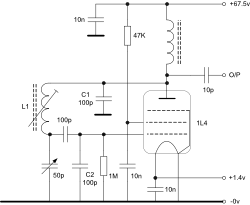
Adequate isolation must be provided to buffer the circuit from that which follows. 1L4 and 1T4 valves both worked well. The anode RF choke was 47uH which should be increased for lower frequencies.