Valve Circuits 4
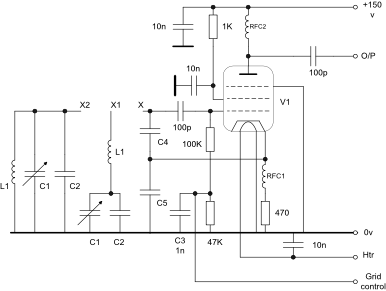
The above circuit can be configured as:
- a high-
C Colpitts by joining X directly to X2 - a medium C Colpitts by joining X to X2 via a capacitor similar in value to C2
- a Clapp by joining X directly to X1
In each case the user must ensure that sufficient gain exists to enable fast starting of the oscillator.
The circuit will cover 1.8, 3.5 and 7Mhz by selection of L1, C1, C2, C4 and C5 as required. For example, C4 and C5 would typically be 1000pF for 1.8Mhz. Values may be switched for different bands but the switch should have a ceramic wafer and substantial and clean contacts for reliable operation.
The circuit time constants are sufficiently fast to allow for direct keying using the grid blocked circuits elsewhere on this site. Drive level to the next stage will not be high but adequate. If a very minimalist design is required RFC2 can be replaced with a tuned circuit resonant at twice the oscillation frequency when used on the higher frequency bands, for example a 7Mhz VFO generating output on 14Mhz -
The mechanical construction is absolutely critical for best frequency stability so a strong chassis and front panel, double bearing tuning capacitor and a ceramic coil form for L1 are mandatory. Fixed tuning capacitors should be silver mica.
V1 should be chosen to have a separate suppressor grid connection e.g. the EF50, EF80 and EF91 to maximise isolation.
RFC1 and RFC2 should be different values with RFC1 having the lower value.
The 150V supply should be regulated.
Only one set of each components marked L1, C1 and C2 are required dependant on the chosen configuration.
C4 and C5 should each be at least five times the maximum value of C1 + C2.
1. Grid Block Keyed VFO
3. Keyed HF PA
The circuit shows a single stage power amplifier with a pi tank output network. For AM and CW it may be operated in class C but for SSB it must be operated in a linear mode, typically class AB1, which requires an adjustable negative bias facility which is not shown but may be easily implemented with grid blocked keying = see Valve Circuits 3, Section 1.
Adequate screening and decoupling is required, particularly when the PA and the VFO are on the same frequency i.e. no multiplication is used.
These circuits could, in principle, all be implemented using 1.4V filament valves for a very low power portable application with the appropriate HT voltages. Types to consider include the 1T4, 1L4, 3S4, 3A4, 3B4 and Russian rod valves like the 1P24B.
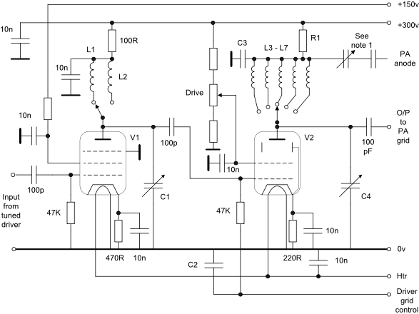
2. Buffer Multiplier Stages
The circuit below shows a two stage circuit containing a low power buffer V1 which can also be a low power multiplier and a higher power buffer/multiplier V2. The function of each stage will depend on the number of bands required by the constructor.
Notes:
1. If neutralisation is required then R1 should be replaced by an RF choke, C3 set to around 470p and the series fixed and preset capacitors included as shown and connected to the anode end of RFC2 in he PA circuit -
2. V1 may be an EF80 or EF91 and V2 a 5763 or similar.
3. The selection of the inductors L1 -
4. C1 and C4 would typically be 20-
5. Keying rise and fall times are determined by capacitor C2 and any series resistance in the keying line.
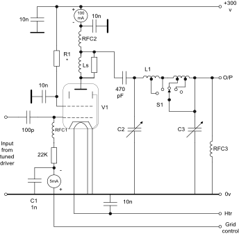
RFC1 is used to prevent damping of the driver tuned circuit by the 22K grid resistor. Ls is two or three turns of wire wound on a solid carbon 1W resistor of 10 -
* For low power operation from ,say, a 300V HT supply the screen may be fed from the anode supply via a small decoupling resistor. However, if higher power operation is contemplated with a higher voltage anode supply then the screen may need to be fed from a separate supply.
For low power operation valves like the 5763 and 2E26 are suitable and still easily available but there are many other types including a number of sweep tubes.
Neutralisation may be implemented if PA instability is encountered. A significant change in PA grid current when the PA anode is tuned through resonance is a good indication that neutralisation is required.