Vackar VFO
Constructing a stable VFO is not rocket science but it does require following some long established principles. A mechanically stable enclosure, good quality and stable components and power supply, a ceramic former for the inductor, dual bearing tuning capacitor, adequate isolation between the tuned circuit and the oscillator circuit etc.
Three versions of this oscillator have been built with the circuit below, two in home made enclosures and one in a Heathkit SB-
To reverse the switching polarity simply reverse the two diodes in parallel with the 22pF trimmers.
e) The VFO components are contained within the screened enclosure. The VFO inductor L1 and 75pF tuning capacitor are mounted directly onto the inside of the metal enclosure, the rest on a fibreglass PC board. The buffer and regulator module are mounted on the outside wall of the enclosure to provide additional isolation. A simple metal screen may be used if required over the buffer and regulator module.
f) The 9v supply is obtained from another Low Drop Out (LDO) regulator fed from the common 12v supply.
g) Ensure that all stages after the VFO oscillator do not saturate otherwise some isolation will be lost.
h) Inductor L2 is very small compared to L1 and is to allow incremental changes to be made for calibration.
i) If you do not require the RIT facility then leave it out. The two varicaps and the adjacent 47pF coupling capacitor should be selected for the desired pulling range. As shown, the RIT control voltage should be positive with respect to the chassis, well regulated and hum free.
j) During development and test, two oscillator devices failed when running on a 9v supply so this has now been reduced to 6v with no further failures.
k) No attempt has been made to obtain a linear dial calibration as a frequency counter is used instead.
l) The Vackar calculator spreadsheet below has been updated to allow a fixed capacitor across the tuning capacitor to be specified and included in the various calculations. The default model contains different value capacitors to that shown in the circuit above.
m) Some versions of the above circuit showed signs of being slow to start, probably because of the low supply voltage (6v). If this is the case, reduce the 2K2 source resistor to 1K and ensure that starting is reliable.
Version 1: built in a Heathkit LMO enclosure.
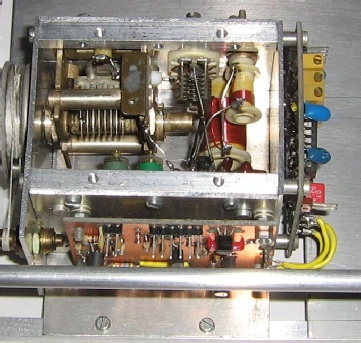
Vackar VFO in Homebrew Enclosures
2. Non-
a) The horizontal width of the enclosure is 2.9 inches.
b) The PC board nearest the camera holds the buffer and regulator. The PC board on the right holds the transmit receive RIT, offset logic and 9v regulator.
c) The small inductor inside the enclosure is the fine adjust with the main inductor below it. The dual bearing tuning capacitor is from an old WWII RF27 unit, given an initial wash, immersion in a silver dip liquid followed by another wash, dry and lubrication of the bearings and sliding contacts.
d) The enclosure is made from 16swg NS4 half hard aluminium sheet fixed to 0.25inch square aluminium bar using 6BA tapped holes. The complete enclosure is extremely strong and does not move!
Circuit:
a). Capacitors marked * have a direct effect on the frequency of oscillation and should be qood quality and stable with temperature. Fixed values should be silver mica. Avoid sub miniature leaded ceramic types. The variable capacitor should be a dual bearing type. I have used two from Heath LMOs and one from a WWII RF27 unit -
b) D1 = BA244 or similar VHF band switching diode
c) The offset switching components shown provide the same functionality as in the SB101 for offsetting the VFO between USB and LSB. An additional set of offset components will be required if you wish to have a different offset on CW.
d) As shown, the offset switch requires a positive voltage to reverse bias it and a negative voltage to activate it -
e) This version drifted a maximum of 300Hz in ten hours from a cold switch-
3. VFO with a Heathkit LMO Tuning Capacitor
The following photo shows the third version that uses some components from an SB-

a) The output frequency range is 5.9 -
b) The PCB on the left contains the oscillator, offset and RIT circuits and FET buffer. The PCB at the top contains the main output buffer, 6v low drop out low noise regulator and six pin power and control connector which projects through the side wall.
c) The two preset controls on the lower box edge are the fine adjust trimmer and fine adjust inductor.
d) The 6:1 epicyclic drive plus the original Heathkit worm drive gives a final tuning rate of 16.6KHz per revolution and is smooth to operate.
e) This version regularly shows total frequency drifts of 300 -
f) The output stage is a complimentary emitter follower with a low output impedance. Connecting a 47ohm resistor to the unloaded output shows no change in frequency to the nearest Hertz.
