Useful Formulae
Tuned Circuits
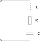
1. The basic parallel resonant tuned circuit on the right includes a resistor representing the circuit losses. In practice the losses in the capacitor are significantly less than the inductor and can usually be ignored.
a) Resonant frequency: f = 1 / (2 * pi * sqrt(L * C))
b) Quality factor: Q = (2 * pi * f * L) / R and may also be expressed as
Q = Fc / (Fh -
c) Dynamic resistance at resonance = L / (C * R) ohms.
d) If you wish to move the resonant frequency of a tuned circuit from f1 to f2 using the same value of inductance then the new value of capacitance (C2) that is required can be calculated from the formula: C2 / C1 = (f1 / f2)2 and this can be re-
Where f1 is the resonant frequency for L and C1 and f2 is the resonant frequency for L and C2 i.e. L is the same value for both frequencies.
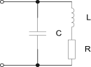
2. The basic series tuned circuit on the right also includes a resistor to represent the circuit losses, primarily in the inductor.
a) Impedance at resonance = R ohms.
All component values are in basic units i.e. Farads, Henries, Ohms etc.
pi = 3.142
More to follow ….