Typical Receiver Block Designs
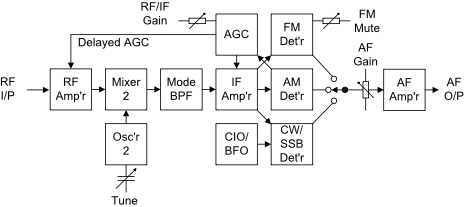
4. The following block diagram shows, in simplified form, the major building blocks of a typical Tunable IF communication receiver used in amateur radio stations from the 1960s onwards and capable of multi-
6. The various functional blocks shown above may be assembled individually from own designs or kits that are available from commercial suppliers. Consideration must be given to the design of modules that may require to be bi-
For SDR (Software Designed Radios) the reader should search for ‘SDR designs’ on their preferred Internet search engine.
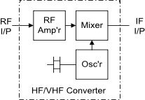
The main receiver is shown above to the right and the crystal controlled converter to the left. The receiver will cover a single tuning range which may be an amateur band or not and the converter will cover as many ranges as is required. During the late 50s to the early 70s this was a well used technique used iin multiband HF and VHF transceivers. However, in the late 70s this receiver technique on the HF bands was replaced by designs using synthesised local oscillators and usually a single frequency conversion to the IF containing the main selectivity block in order to improve the dynamic range. However, local oscillator noise in the synthesiser restricted the overall dynamic range that could be obtained. See 6 below.
The RCA AR8516 used this architecture to implement a multiband LF to HF receiver.
Much improved mixer and filter design from the 90s onwards means that the tunable IF is still an option for good receiver performance without the use of synthesiser techniques and their attendant noise problems. The H-
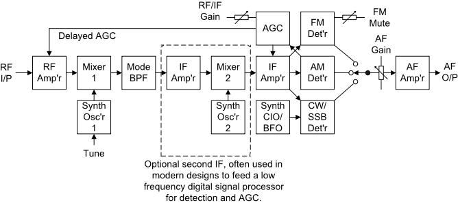
5. The following block diagram shows a dual conversion communication receiver with synthesised local oscillators. The second IF is optional but does provide a mechanism for providing mode filters and significant gain at a lower frequency with a minimal risk of instability.
For continuous coverage receivers the first IF needs to be outside the receiver tuning range and is frequently in the 40 -
To reduce synthesiser VCO noise a UHF VCO is used which is divided down to the required frequency.
However, for HF amateur band only applications a first IF of 9Mhz is popular as crystal filters are available commercially and may also be designed and made by home constructors.
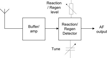
1. The block diagram to the right shows, in simplified form, the very few building blocks required for a simple regenerative or reaction detector. Since both types can cause interference to other band users the use of an RF stage is recommended to isolate the detector from the aerial.
This is a very simple type of receiver to build but has limitations that will become apparent in use. For example, at the threshold of regeneration even low level signals can have a significant effect on operation.
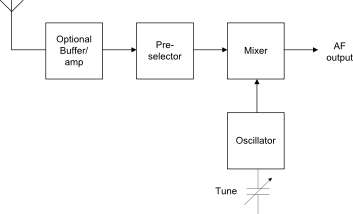
2. The block diagram to the right shows, in simplified form, the building blocks required for a simple direct conversion receiver suitable for the reception of CW and SSB signals. It is not suitable for AM or FM signals.
The optional RF stage will reduce local oscillator leakage and increase the sensitivity for weak signals but also increase the overload characteristics with strong signals so some form of gain control may be required.
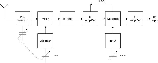
3. The block diagram below shows the building blocks required for a basic single conversion superhet receiver. This was the norm for most medium and long wave broadcast receivers (without the BFO) and was developed further during WWII to produce receivers like the AR88 and HRO. It has limitations in terms of poor frequency stability and image response on the higher frequencies and was frequently used as a tunable IF for a crystal controlled converter that significantly improved its performance -