Surge Limiter
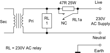
1. This limiter is used where there is a significant switch on surge compared to the normal current consumption. The values shown were used in a 1100V 400mA plus a 420V 200mA DC power supply to limit the inrush current while the smoothing capacitors are initially charging and typically takes about one second to activate the relay. Values may may need to be selected depending on the actual mains voltage and currents involved in the constructor’s equipment. The particular relay used mounts on a PC board and has DPCO contacts each rated for 8A at 240V AC and wired in parallel. Select the relay voltage to suit your local mains voltage (120/240V).
The 47ohm (example value) series resistor limits the inrush current to a reasonable value and during that period the voltage drop across the resistor means that there is insufficient voltage to energise the AC relay. As the surge current reduces in value the AC voltage across the primary of the mains transformer increases until it is sufficient to energise the relay and short out the series resistor. The resistance and power dissipation will depend entirely on the individual application so be prepared to try different values.
The series resistor should be a metal cased type that can be bolted down to the chassis and should be capable of absorbing the peak current, the resulting voltage drop and power dissipation and the voltage between the centre connection and case. If in doubt err on the large size in terms of dissipation. You may need to use a 50W or 100W depending on the application.10W aluminium clad resistors may not have a sufficiently high breakdown voltage so check the specification.
The resistor value and dissipation may be changed for use with higher or lower consumption power applications and on a 115V supply. A separate limiter should be used for each mains transformer requiring surge limiting in a power supply.
This mechanism is not suitable for unattended applications or where there is a high constant current into the mains transformer primary winding compared to the peak value although it should be fine for use with filament transformers by proper selection of the value of the current limiting resistor.
An example PCB layout may be downloaded from here.
2. If this simple current limiter is not suitable for a particular application then a timer mechanism may be used instead which will require a small separate mains transformer to supply a low voltage regulated supply for a 2 -
Always err on the side of safety.