Solid State Circuits 9 -
Version 5.7 (hopefully the final version!) Is shown in the above circuit. The construction has been simplified and the layout amended from previous versions to correct some minor errors in component spacings and labeling. The squarer now uses three separate ultra high speed 5 volt inverters type NC7SZ04 to improve the VHF response and reduce the current consumption above 50MHz. The version 5 PCB layout document is available here -
A through hole component PC board as well as a surface mount component PC board of a similar size have been developed and will be shown here as soon as manufacture and tests are complete.
Warning: The seven surface mount ICs used in this version are more fragile and susceptible to damage from excess voltages, electrostatic charges etc compared to previous versions. It is recommended that each module be completely isolated from all equipment before any work including soldering is carried out. I have inadvertently damaged several ICs by not following these rules.
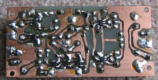
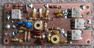
A hand made PC board is shown below.
This page shows my latest version of the H-
The original mixer design may be found at: CDG2000 Transceiver.htm
IK4AUY has also done significant work on the H-
The latest work by PA3AKE can be seen here.

I have now completed a PCB layout and had some commercial PC boards made with seven SMT ICs and the rest being through hole components. As soon as they have been populated and tested a photo will be shown here.