Solid State Circuits 1 -
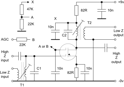
1 MOSFET RF/IF Amplifier
The diagram to the right shows a single stage MOSFET tuned amplifier which may be used as a preamplifier, RF or IF amplifier. Depending on the frequency of operation, the gain will be from 15dB to 30dB -
Decoupling values are typical for operation on the HF bands.
Two bias options are shown -
Notes:
- The tuned frequency will be controlled by L2 / C1 and L3 / C2 and for most purposes these can be made the same value, I.e. C1 = C2 and L2 = L3. The capacitors used for high impedance coupling applications will typically be significantly less than the values of the tuning capacitors C1 and C2.
- Additional RF selectivity may be implemented by using a multi-
section bandpass filter instead of the single tuned circuit that is shown. - The low impedance points will be determined by the turns ratio of L2 : L1 and L3 : L4 which would typically be between 7:1 and 10:1 for a 50 ohm environment.
- If this amplifier is required to be manually tuned from a front panel control then C1 and C2 should be variable and ganged together with C2 connected between drain and ground instead of as shown -
a DC isolating capacitor may be used if required. - If this amplifier is to be used ahead of the crystal set shown elsewhere on this site then the tuned circuit comprised of C2 / T2 should be replaced with an RF choke and the High-
Z output connected to the tuned circuit in the crystal set. C1 should be ganged to the tuning capacitor in the crystal set. - Keep the input and out circuits apart and if necessary, put a screen between the two to ensure stability. The inductors may be mounted in screened assemblies.
2. As the 40673 is now very difficult to obtain it may be substituted with another type of dual gate MOSFET including a more modern device like the BF960 or one of the 3N20x series. In this case check the operating characteristics to ensure that the voltage and current ratings are not exceeded. Alternatively a cascode circuit using a low noise n-
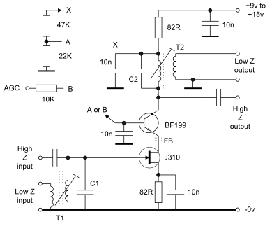
During tests, some UHF instability was noted in the BF199 and a test MPSH10 which did not seem to be greatly affected by circuit layout or decoupling so a ferrite bead was put onto the emitter leg of the NPN device which cured the problem*.
An IF amplifier consisting of three of these stages was constructed on a double sided PC board and produced about 100dB of gain at 9MHz. A lot of care is needed with the layout to ensure stability.
Additional selectivity or filtering may be required to reduce the wideband noise at the output. The biasing may need to be adjusted for different supply voltages.
As there are two devices in series fed from the 9v line the output level of the upper device will be relatively low so operation may be better on a higher voltage supply, say 15v. The 47K and 22K bias network will require changes for different supply line voltages and devices. On a 9v line I use 3K9 and 4K7 respectively which also reflects the lower hfe of the BF199 and the resulting higher base current .
*The ferrite bead is intended to suppress UHF oscillation but if this proves impossible then try a BF173 or a 2N3904 instead of the BF199 -
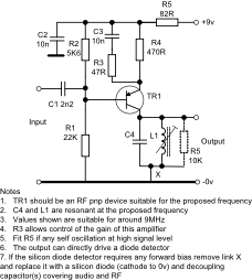
3. The circuit to the right is convenient to directly drive a diode detector for AM or AGC applications. Link X may be replaced with a diode (cathode to 0v) and decoupling capacitors if the detector diode requires some temperature compensated forward bias.
The undecoupled emitter resistor R3 may be used to control the overall gain of the stage.
With some transistors I have occasionally seen the circuit oscillate after over-