Power Supply Cooling
My BNOS 12/25A power supply has performed well over many years but tends to run very warm on constant power modes like FM and in hot summers so I decided to add a thermostatically controlled cooling system with a fan on the rear heatsink and a small internal fan to move the air within the enclosure. The circuit is shown below and based on a similar circuit elsewhere on this website but with the current switching capacity increased to 200mA in order to use two 12V fans.
The overall installation can be seen below:
The controller board may require a resistor change depending on the resistance of the thermistor at the required temperature -
The maximum controller output current was increased by reducing the original 8K2 feeding the base of the BFY51 to 2K2 which reduced the collector emitter saturated voltage to 600mV when passing 180mA. The controller circuit is fed from an unregulated 23V DC supply which the onboard 7812 regulator will reduce to 12V. A 22ohm 5W wirewound resistor was added in series with that supply to reduce the inrush current when the fans are first energised and reduce the energy dissipated in the 12V regulator -
After about 15 minutes of continuous fan operation the BFY51, 7812 and 22ohm resistor are just warm to the touch.


The photo above shows the large fan on the outside of the rear heatsink and the small fan inside on the bridge rectifier heatsink -
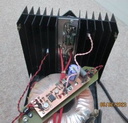
The photo above shows the controller board with the twisted pink connecting wires going to the temperature sensor head mounted in the inside of the large heatsink. The controller board is mounted on a piece of plain fibreglass 1/16inch sheet which is supported on two pieces of 2BA threaded studding.
The photo on the right shows the components required to construct the temperature sensor plus the Araldite two pack epoxy adhesive used to retain the thermistor inside the tubular solder tag. The thermistor wires are cut back to about 10mm in length and soldered to the pink twisted wires -
