Inductors and Tuned Circuits
1. Making high Q inductors is generally thought to be a daunting task but in practice there are some fairly basic rules to follow. I will show a number of inductor examples on this page with some measured results. Generally the most difficult problem is getting a high Q in a small space.
The first inductor assembly shown below is an early prototype for a lifeboat emergency transceiver from the 1970s. The former is made of fibreglass and the two sets of windings shown are for 500KHz on the left and 2182KHz in the centre (the 8MHz inductor that was on the right is missing). Approximately 110 strand enamelled and cotton covered Litz wire was used and the 500KHz winding used a distributed wave winding technique to minimise the self capacitance and maximise the Q -

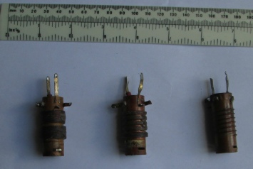
2. Photo 2 shows three Wearite air cored inductor assemblies, type PA1 (long wave), PA2 (medium wave) And PA4 (a short wave band). Each assembly consists of a tuned winding and an aerial coupling winding. Note that with the two lower frequency types where the aerial is usually very short compared to a quarter wavelength and therefore exhibits a capacitive impedance the aerial windings have a relatively high inductance. The short wave assembly has an aerial coupling winding that is small compared to the tuned winding. Measurements were made on a Marconi TF1245A Q Meter.
|
Type |
Tuning Capacitance |
Resonant Frequency |
Q |
|
PA1 |
300pF |
148KHz |
48 |
|
PA2 |
300pF |
668KHz |
82 |
|
PA4 |
100pF |
21.72MHz |
58 |
|
PA4 |
300pF |
12.7MHz |
40 |
These were made primarily for the home construction market for a frequency range of 100KHz to 30MHz and were available for TRF receivers and with matching oscillator inductor assemblies for superhet receivers with an IF of about 455KHz.
3. Standard Resonators
Many years ago I developed a range of standard resonators that may be used in a wide range of applications covering 77KHz to 205MHz. The assemblies from which they are made were manufactured by Neosid UK and were in common use in mobile radio communications equipment in the 1960s and 1970s. They are still available, usually mounted on scrap PC boards or similar at radio rallies.
An attached document here shows their construction and test results.
4. Example Inductor Assemblies
The following assemblies are in regular use in my home construction activities:
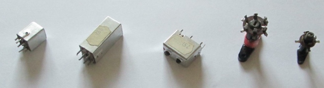
From left to right:
- First item from left is a single assembly manufactured by Neosid in the 1960s and 70s and available with 5 or 6 pin base, threaded bakelite former, aluminium can, ferrite or dust iron cup core and ferrite or dust iron core. Still available on assemblies from old mobile radio equipment
- Double height version of item 1 with space for two tuned circuits
- Double width version of item 1 with a 6 pin base
- 3/8inch diameter threaded bakerlite former with dust iron core and wiring support
- 1/4inch diameter threaded bakelite former with dust iron core and wiring support
Items 2 and 3 from the left were purchased from J Birkett in 2016/17
Items 4 and 5 from the left were available from Denco (Clacton) Ltd before they closed some years ago. Seen occasionally at radio rallies.
Cores are retained with silicon tap grease so that they may be retuned without breakage but will not move with vibration. Always use a tuning tool that has a good fit with the core. Diagonal end shapes should be avoided as they risk breaking the core.
5. Example Inductors
These are all wound on 0.25 inch (6.3mm) diameter bakelite formers with dust iron tuning cores and the results measured with no screening can in place. The can is 0.75 x 0.75 x 2.5 inches (19 x 19 x 63mm) and has very minor effect on the results. These screened assemblies were in common use in early valve televisions, VHF FM receivers and valve mobile radios and can often be seen at amateur radio rallies.
The wire guage should be chosen to get a winding width of about the same or slightly longer than the length of the core in order to obtain a good Q and a reasonable tuning range.
The measurements were made with a Marconi TF1245A Q Meter and its associated TF1246 RF Oscillator.
|
Turns |
Wire size |
Winding Width - |
Tuning capacitor - |
Frequency with core out - |
Q |
Frequency with core in - |
Q |
|
100 |
7 strand Litz 30turns flat + 70t scramble wound on top |
0.5 |
220 |
1.5 |
126 |
1.13 |
200 |
|
150 |
1.82 |
140 |
1.35 |
205 |
|||
|
100 |
2.2 |
136 |
1.6 |
172 |
|||
|
48 |
7 strand Litz scramble wound |
0.5 |
220 |
3.15 |
95 |
2.3 |
180 |
|
100 |
4.3 |
124 |
3.39 |
175 |
|||
|
22 |
30swg |
Fixed |
100 |
9.6 |
112 |
7 |
120 |
|
15 |
0.5mm |
Fixed |
82 |
16.3 |
112 |
11.5 |
110 |
|
12 |
0.5mm diameter |
by wire size and number |
100 |
16.6 |
125 |
12.6 |
120 |
|
68 |
20 |
125 |
15.2 |
100 |
|||
|
47 |
24.4 |
116 |
18.3 |
120 |
|||
|
10 |
0.8mm diameter |
of turns |
47 |
30 |
124 |
23.2 |
122 |
|
33 |
39.6 |
127 |
29 |
116 |
|||
|
7 |
0.8mm |
Fixed |
39 |
45 |
98 |
31 |
101 |
Constructors wishing to use these examples should remember to allow for circuit and stray capacitances which may need to be measured for accuracy. Where a pair of coupled inductors is to be wound for a double tuned IF transformer or band pass filter the inductors should be spaced apart by at least the width of each winding and tested in circuit to obtain the correct coupling factor.
When each winding has been tested and found to be correct it should be fixed in place with a low loss varnish and dried thoroughly. I use an oil based polyurethane varnish and dry each assembly on a house hold radiator for 24 hours.

The assembly on the right is a newly wound and varnished IF transformer for 3.2MHz with two separate tuned circuits and iron dust cores. Each winding consists of 38 turns of 7 strand cotton covered litz wire scramble wound on the 0.25 inch diameter former with a 220pF tuning capacitor. As this is intended for use in valved equipment with a 250-