IF Filters 1
1. Lattice Filter at 3.395MHz
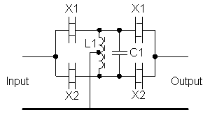
The above is comprised of two half lattice filters connected back to back so that only a single tuned circuit is required. Lattice filter design theory requires the internal series and parallel resonant frequencies (subtract to get the pole zero spacing) of each crystal lie at specified points on the required passband. Specifically, the lower frequency crystal should have its series resonance on the LF edge of the passband and its parallel resonance at the centre of the passband and the higher frequency crystal should have its series resonance at the centre of the passband and its parallel resonance on the upper edge of the passband. The rule of thumb says that the resulting filter bandwidth will be between 1.7 and 2 times the pole zero spacing.
This filter was constructed to see what was possible with standard, off the shelf crystals from Heathkit SB Line units (manufactured during the late 1960s).
|
X1 |
3.3936MHz HC6/U Heathkit SB line CIO crystal |
|
X2 |
3.3964MHz HC6/U Heathkit SB line CIO crystal |
|
L1 |
57+57t 30swg enamelled copper wire bifilar wound on an 0.5 inch diameter Micrometals grade 8 (red) dust iron toroid. |
|
C1 |
2- |
The crystal frequencies are those marked on the cases and are the intended frequencies of oscillation in a parallel mode carrier insertion oscillator. The initial passband showed a 3dB ripple with termination impedance of 2Kohms. An optimum passband ripple of around 1dB was achieved with input and output impedances of 1.1K. The output termination impedance appears to be more critical than the input source impedance.
Test results:
|
Attenuation dB |
LF side in MHz |
HF side in MHz |
|
- |
3.39326 |
3.39674 |
|
- |
3.39310 |
3.39736 |
|
- |
3.39299 |
3.39768 |
|
- |
3.39277 |
3.39801 |
|
- |
3.39205 |
3.39895 |
|
- |
3.39112 |
3.40018 |
|
- |
3.38990 |
3.40204 |
|
- |
3.38850 |
3.40552 |
|
- |
3.38680 |
3.44811 |
The shape and position of the top part of the passband is significantly dependant on the tuning and respective values of L1 and C1. The ultimate stopband attenuation of the filter is about -
Problems with several spurious responses at about 3.5MHz were noted. This is not surprising as these crystals were intended for use in oscillators where the spurious response requirements are less stringent than for filters. It should be possible to significantly improve the performance of this filter using more carefully specified crystals and adding another half or full section. A high Q conventional tuned circuit would also help.
Readers are referred to the ARRL or RSGB Handbooks for more information on the design and construction of half and full lattice filters. 'Single Sideband for the Radio Amateur' (5th Edition 1970) by the ARRL has a more detailed description of the design of lattice crystal filters. More advanvced readers might like to consult "Crystal Filters -
Crystal Parameters:
|
Crystal Marked MHz |
Fs MHz |
Fp MHz |
Cp pF |
Cs fF |
Ls mH |
|
3.3936 |
339623 |
340051 |
5.126 |
23.813 |
92.417 |
|
3.3954 |
339434 |
340170 |
6.376 |
27.649 |
79.515 |
|
3.3694 |
339542 |
340316 |
5.78 |
26.353 |
83.371 |
|
Fs |
Series resonant frequency |
Fp |
Parallel resonant frequency of crystal without any external external added parallel capacitance |
Cs |
Series (motional) capacitance |
|
Cp |
Parallel capacitance |
LS |
Series (motional) inductance |
fF |
Femtofarad (pF/1000) |
|
pF |
Picofarad |
mH |
Millihenry |
|
|
Keys:
A similar format filter has also been constructed using crystals at 3.3936MHz and 3.3954MHz which resulted in a -
A third filter was constructed using pairs of crystals at 3.3954MHz and 3.3964MHz (1KHz spacing) and this produced a poor quality passband characteristic, probably because the internal series and parallel resonant frequencies were not optimised for the narrower passband. A ladder filter may be more appropriate for SSB and CW bandwidths as long as the crystal parameters are correctly specified.
Some additional work needs to be done on crystal neutralising and to determine the optimum L-