Basic Crystal Set
The crystal set is the simplest form of radio receiver but it is also used as one of the building blocks for more complex receivers. It may be constructed from the following circuit diagram. The output level will be very low which is why high impedance headphones are required -
Notes:
- This is an example of an Amplitude Modulated (AM) signal detector -
it will not work with other modes of transmission like Morse, Single Sideband, Frequency Modulation or Digital. - The most easily heard AM transmissions occur on the Long and Medium wave bands (150Khz to 1.5MHz) -
there are many on the Short Wave bands but these may be more difficult to locate for beginners and may be of a considerably lower signal strength. - The receive frequency is determined by the tuned circuit consisting of inductor L1 and capacitor C1.
- C1 will typically have a maximum value of 300pF to 500pF and may be air spaced or a solid dielectric (Polyvaricon) type.
- Inductor L1 should be wound with a series of taps every few turns. The right hand tap connected to C1 will control the tuned frequency. The left hand tap is connected to the aerial and may then be tried on each tap using a crocodile clip until the best results are achieved. L1 should be wound on an insulated former with an outer diameter of 25 -
50mm (1 - 2 inches) using insulated or enamelled copper wire about 26swg. Litz wire will give the best Q factor but is more difficult to obtain so start with something simple to get some initial results. A piece of kitchen waste pipe about 70mm long and 35mm diameter makes an ideal former and the dimensions are not critical. - A good earth is required.
- Best results will be obtained using an OA90 for the diode D1 as it has the lowest conduction threshold of the types specified.
- The circuit may be constructed on a small wooden base with a front panel made from hardboard, fibreboard or a similar material as shown in the following examples. Keep it very simple until you have something working, then tidy it up.

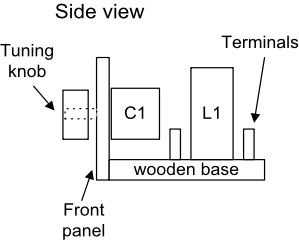
The suggested layout is not critical but sufficient space should be provided between components so that they are easily accessible.
The tuning capacitor will have a control shaft diameter of either 6mm or 0.25 inches depending on its age.
A control knob mounted on the shaft will make tuning much easier.
The number of turns required on inductor L1 for a given frequency will depend on the maximum value of the tuning capacitor C1 -
The 1n (1000pF) capacitor may be mounted on the headphone terminals and the diode D1 connected directly to one end of L1 and one headphone terminal -
Constructors may wish to experiment with the number of turns on L1 and the aerial coupling in order to get the best results. Instead of aerial taps a coupling winding could be employed. This is all part of the fun of learning by trying.
When used in a more complex receiver The capacitor value is usually fixed and the inductor mounted in a screened assembly with a ferrite or iron dust tuning core.
A simple tuned amplifier may be added to the above circuit to increase both the sensitivity and selectivity.
