Crystal Measurements for IF Filters
1. A series of measurements was made on a range of crystals and a few ceramic resonators and the results are shown in the table below. These results are useful for:
- the design of ladder filters -
columns 4,5,9 & 10 are required when using the Giangrandi web site - tunable crystal oscillators whether by capacitor or varicap diode
- The design of full lattice and half lattice filters using columns 9 and 10
The measurement set up is shown first.
|
1 |
2 |
3 |
4 |
5 |
6 |
7 |
8 |
9 |
10 |
|
|
|
Series Resonant Frequency in MHz with the following value for C1 in pF |
Parallel Resonance |
||||||
|
Freq. MHz |
Type/Pkg |
4p7 |
10p |
27p |
56p |
120p |
220p |
Short circuit |
Short circuit |
|
2.45 |
CR |
2.5022 |
2.4835 |
2.4482 |
2.4182 |
2.3902 |
2.3741 |
2.3506 |
2.5245 |
|
2.4576 |
X / 3 |
2.4584 |
2.45798 |
2.45764 |
2.4575 |
2.45744 |
2.4574 |
2.45738 |
2.45993 |
|
2.5 |
X / 2 |
2.50091 |
2.50044 |
2.50005 |
2.49989 |
2.4998 |
2.49977 |
2.49972 |
2.5026 |
|
3.39 |
X / 1 |
3.39151 |
3.39078 |
3.39018 |
3.3899 |
3.39876 |
3.3897 |
3.38962 |
3.39415 |
|
3.39211 |
X / 1 |
3.39347 |
3.39276 |
3.39216 |
3.3919 |
3.39175 |
3.39169 |
3.39163 |
3.39635 |
|
3.39895 |
X / 1 |
3.40072 |
3.3998 |
3.39903 |
3.3987 |
3.39853 |
3.39844 |
3.39834 |
3.4043 |
|
3.39895 |
X / 1 |
3.40074 |
3.3998 |
3.39903 |
3.39869 |
3.39851 |
3.39842 |
3.39832 |
3.40443 |
|
3.57954 |
X / 1 |
3.5817 |
3.5804 |
3.57925 |
3.57877 |
3.57852 |
3.57838 |
3.57825 |
3.58613 |
|
7.055 |
X / 1 |
7.06077 |
7.05813 |
7.05558 |
7.05438 |
7.05364 |
7.05336 |
7.05039 |
7.0677 |
|
9 |
X /3 a |
9.00682 |
9.00362 |
9.00078 |
8.9996 |
8.99885 |
8.99865 |
8.99824 |
9.0159 |
|
9 |
X / 3 a |
9.00726 |
9.0038 |
9.00094 |
8.99953 |
8.99887 |
8.99861 |
8.99817 |
9.01712 |
|
9 |
X / 5 b |
9.00757 |
9.00407 |
9.00083 |
8.9994 |
8.99858 |
8.99821 |
8.99776 |
9.01696 |
|
10 |
X / 4 |
10.00812 |
10.00424 |
10.00084 |
9.99938 |
9.99848 |
9.99816 |
9.99789 |
10.01909 |
|
12 |
X / 4 |
12.00825 |
12.00437 |
12.00076 |
11.99896 |
11.99794 |
11.99755 |
11.99707 |
12.01772 |
|
12 |
CR |
12.26818 |
12.16535 |
11.999 |
11.8937 |
11.81071 |
11.7739 |
11.71744 |
12.41283 |
|
14 |
X / 3 * |
14.01561 |
14.01035 |
14.0057 |
14.0037 |
14.00242 |
14.00196 |
14.00113 |
14.02909 |
|
20 |
X / 4 * |
20.01398 |
20.00707 |
20.0014 |
19.99847 |
19.99724 |
19.99675 |
19.99586 |
20.0326 |
|
20 |
CR |
20.00876 |
19.9901 |
19.96921 |
19.9562 |
19.94966 |
19.94618 |
19.93958 |
20.03948 |
|
37.5 |
X/SMT * |
N/A |
37.501 |
37.492 |
N/A |
N/A |
N/A |
37.484 |
37.547 |
Type/Package Keys:
|
CR |
Ceramic Resonator |
X |
Quartz crystal |
* |
High side spurious noted |
|
1 |
HC6/u solder seal |
3 |
HC18/u solder seal |
5 |
HC18/u size resistance weld |
|
2 |
HC6/u size cold weld |
4 |
HC18/u size cold weld |
a |
IQ Designs non matched series |
|
b |
PA3AKE low dust high IP3 type |
N/A |
Not available |
SMT |
Surface mount |
Notes:
- This information is based on sample sizes or one or two so readers should use it as an indication of what is possible and conduct their own tests on their own components for more precise results.
- Trailing (right hand) zeroes in all frequencies have been omitted.
2. If you build a number of different bandwidth ladder filters using the same frequency crystals you will find that the centre frequencies are different -
The problem with that scenario is that placing a capacitor in series with a crystal will modify the equivalent motional component values of the crystal and capacitor combination -
One solution that I have tried is to design and construct the required series of filters and measure the resulting frequency responses including the centre frequency. This will provide a good indication of the increase in frequency required to match the centre frequencies of each filter. From these tests you can then try a series of fixed capacitors in series with the chosen crystals to determine the value required to achieve the increase in frequency for each type of filter. Having determined the capacitor value required for each type of filter you can then measure the new motional values with the series capacitor in place.
As an example, I designed and constructed three different eight section filters with bandwidths of 7.5KHz, 2.1KHz and 1KHz and 0.5dB maximum passband ripple using a collection of low cost HC18/u crystals marked 8.863256MHz selected to have their series resonant frequencies within 100Hz of each other. Measuring the filters showed the centre frequencies to be 8.864792MHz, 8.860506MHz and 8.859488MHz respectively so the 2.1KHz filter centre frequency was 4.286KHz low and the 1KHz filter was 5.304KHz low compared to the 7.5KHz filter.
Tests determined that a series capacitor of 18pF was required for the 2.1KHz filter and 15pF for the 1KHz filter to make their centre frequencies the same as the 7.5KHz filter. As this significantly modified the equivalent motional component values, I redesigned the two filters using these new values. The test results show that the new centre frequencies are now within a maximum of 200Hz of each other and the 2:1 shape factors are at least -
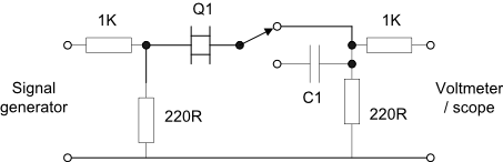
The switch is shown in the short circuit position.