Crystal Filters
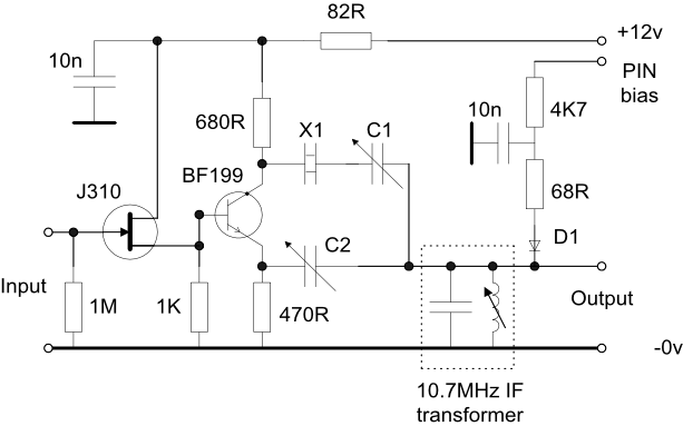
1. Single Crystal Filter The following circuit is a single stage neutralised crystal filter at 10.7MHz although the principle may be used at any frequency for which crystals are available. Standard over the counter crystals showed signs of spurious responses close to the passband so some 10.7MHz mobile radio filters were disassembled and crystals selected for the same or very close series resonant frequencies. This format filter was in common use in early communication receivers during and after WWII, typically at 455KHz.
The bandwidth is set by the the equivalent impedance of the parallel tuned circuit in parallel with the resistance of D1, a PIN diode, controlled by the positive PIN bias voltage, typically 0 -
Capacitor C1 (typically 3 -
This type of filter section was developed for a spectrum analyser and was also used, less the PIN diode facility, and with the appropriate tuned circuit values to remove most of the modulation from the 198KHz frequency standard signal prior to being applied to the phase locked loop of an off air frequency standard.
For an analyser, four or five of these filters may be cascaded in order to get added selectivity and stop band attenuation. The first section should be preceded by an LC filter at the filter frequency to protect the solid state devices from broadband signals typically found in an analyser.
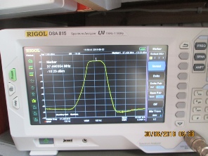
2. 37.5MHz Filter
An eight section ladder filter was designed and constructed using 37.5MHz fundamental mode crystals and the photo to the right shows the frequency response. The -
The design is based on an 0.1dB ripple Chebychev model and the characteristic impedance of the filter is 68ohms.
The crystals were not matched but early measurements showed the series resonances to be very close.
A 15KHz wide version to pass 25KHz channelised FM signals and a common PC board layout are in development.
3. Ladder Filters
A ladder filter is relatively easy to design as long as you can measure the basic parameters of a given crystal as shown here and is very easy to construct. However, there are two disadvantages of which you should be aware:
- The attenuation characteristic is less steep on the low frequency side and this is more obvious in filters with a small number of sections so use the maximum number of sections that you can accomodate.
- The maximum bandwidth is a direct function of the L/C ratio of the internal motional parameters of the chosen crystal. For example, at 9MHz the maximum -
3dB bandwidth was 10.339KHz. There is a table of typical values here. - Filters of different bandwidths made with crystals of the same nominal frequency will have slightly different centre frequencies -
the wider the bandwidth the higher the centre frequency. For example, using 9MHz HC18/u crystals the following centre frequencies were noted to the nearest 100Hz:
Bandwidth |
Centre Frequency |
|
600Hz |
8.9976MHz |
|
1.2KHz |
8.998MHz |
|
2.4KHz |
8.9988MHz |
|
6KHz |
9.0017MHz |
Limited increases in the centre frequency can be achieved by adding a low value capacitor in series with each crystal but this extra capacitor changes the equivalent motional values and therefore the overall characteristics of the filter. This additional capacitor should have a high Q (low loss factor) and a very low temperature characteristic so hi-
It may be possible to use a series inductor to lower the frequency a little but the Q of typical inductors are much lower than that of capacitors so the effect on the filter characteric will be significantly more.
Modern low profile crystals use a cut which results in a much higher LC ratio of the motional equivalent values and a much lower maximum bandwidth when used in a ladder filter. Some comparative results have been added to the example crystal measurement listed here. The same problem occurs in crystals used on an overtone compared to their fundamental frequency.