Crystal Calibrator
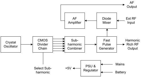
The block diagram below shows the stages required to provide a crystal controlled signal source, AM signal detector and a heterodyne wavemeter. This is a useful instrument that can produce a wide spectrum of stable frequencies.
Notes:
- The oscillator can run at 1, 2 or 10MHz. Temperature compensated or oven controlled oscillators will provide significantly improved frequency accuracy.
- The CMOS divider chain should be selectable in steps of 2 and 5 so that the sub-
multiple frequencies from say 1MHz will be in the form 500KHz, 100KHz, etc down to at least 5KHz. - The sub-
harmonic combiner should use very narrow pulses so as to improve the HF and VHF output levels. - The fast pulse generator is used to produce high output levels at VHF. It can be a high speed switching device, 74S series IC or a step recovery diode.
- A sample of the output from the pulse generator is applied to the diode detector which acts as a mixer to provide an audio output equal to the difference between the RF Input signal and the nearest harmonic. The diode detector may also be used as an AM detector.