Amplitude Modulators
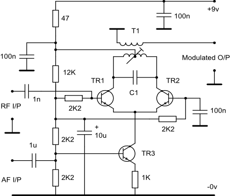
1. The following circuit is an example of a low level amplitude modulator. It may be used in a multimode transmitter to avoid the need for unbalancing the balanced modulator and is not critical in its adjustment or operation.
Notes:
- TR1 and TR2 should be RF devices suitable for the required frequency e.g. BF199. TR3 is an audio device like the BC108.
- RF decoupling values shown are suitable for HF operation from 500Khz to 30Mhz.
- The original circuit used CA3028 or CA3053 ICs which are now difficult to obtain. However, a transistor array IC like the CA3054, which contains six transistors configured as two long tailed pairs, would be fine in principle and is still available.
- The upper two devices act as a phase splitter with single ended input, push-
pull output and modulation achieved by varying the constant current source. No balancing or matching was attempted or found to be necessary in the discrete version although the transistors in the original ICs would have been fairly closely matched as a result of the manufacturing process. - The primary of T1 should resonate with C1 at the required frequency of operation. The turns ratio of T1 will depend on the load impedance. The original prototype at 9Mhz used 9+9t bifilar on the primary and 3t on the secondary. A screened tuned circuit or a toroid are both suitable forms of construction.
- The emitter of TR3 is left undecoupled to provide negative feedback at audio frequencies.
- The circuit was tested with 25mV pk-
pk RF input and 1.1v pk- pk audio input which resulted in 100% modulation and 800mV pk- pk modulated output. - The circuit should not be over-
driven at RF. - Some form of RF decoupling may be required at the base of TR3 depending on the particular application.
- The 9v supply should be reasonably stable and hum free.
- This circuit could be re-
arranged as a single balanced modulator but a manual balance control would be required in the emitters of TR1/TR2 and TR3 would need to be an RF device. The CA3054 could be used to provide both an AM modulator and a balanced modulator or a dual balanced modulator for a phasing SSB generator. The author has not tested this idea yet.
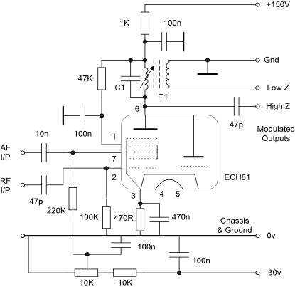
2. The following circuit provides good amplitude modulation to around 90% depth before significant distortion becomes apparent. The ECH81 is particularly useful as the triode and heptode sections are not connected internally although they do share a common cathode which should be decoupled to RF. Decoupling the cathode and G2/G4 to audio did not appear to make a significant difference to the modulation level.
The preset potentiometer should be adjusted for the best modulation envelope shape and this typically occurs when the unmodulated output level is around 40-
The 3.395Mhz tuned circuit connected to pin 6 consists of 30 turns 9/47 strand Litz wire on a one quarter inch diameter former with a dust iron tuning core and a tuning capacitor of 270pF. Litz wire is not mandatory but does give a higher Q than single strand wire at LF and low HF. The choice between high and low impedance outputs will be determined by each users individual requirements.
Other heptodes should function in a similar manner. The author noted considerable envelope distortion when the AF and RF inputs were swapped over and this was not pursued further. A similar circuit was tried using control grid modulation with an E180F pentode but the distortion on the modulation troughs was worse than with the heptode.