AF Filter
Notes:
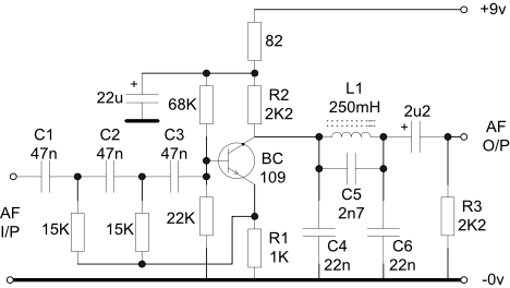
- Capacitors C1 to C6 inclusive should be polyester or polycarbonate +/-
5%. Hi- k ceramic types are not suitable. - Stages may be cascaded for additional stop band attenuation or different bandwidths.
- A similar format filter may be used for CW with the values scaled to reduce the passband to say -
6dB at 600Hz and 1500Hz. R2 and R3 will need to be recalculated for the new filter values. - R1 is always half of the value of R2 to maintain an overall in-
band gain of X1. - Equivalents to the BC109 may be used but they should have low noise and high hfe.
- Resistor R3 provides the correct terminating impedance for the m-
derived pi section low pass filter. The following stage should have a much higher input impedance to avoid loading the filter.
1. This filter, as shown, has been designed to have a bandpass characteristic with an overall gain of one and a frequency response of -