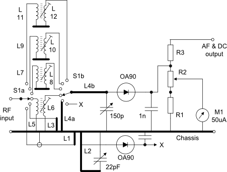
1. The following circuit is based on a commercial design of mine from the 1970s covering 0.8 - 500MHz in six switched ranges. The sensitivity is slightly reduced on the highest range because the diodes are connected in series - this can be solved by adding an extra switch wafer to select the appropriate diode output on each range but this results in extra cost.
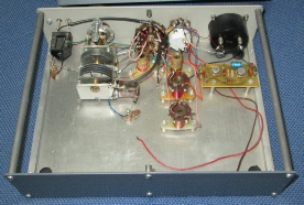
The photo on the right shows an internal view of the instrument. This version includes the op-amp buffer (shown below) which increases the sensitivity by reducing loading on the detectors and tuned circuits. The PP9 battery has been temporarily removed for clarity.
The 200 - 500MHz range uses a U shaped piece of copper strip for the resonator inductor. The low frequency inductors are lifted above the chassis to maximise their Q.
The 50-150MHz inductor is part of the interconnection between the range switch, tuning capacitor and ground connections.
2. DC Buffer
The circuit below uses two single op-amps (or one dual) to increase the sensitivity of the wavemeter by significantly reducing the loading on the tuned circuits as described above.
Both op-amps are set to unity gain and non-inverting. IC1 buffers the DC signal from the wavemeter and IC2 provides a virtual split supply.
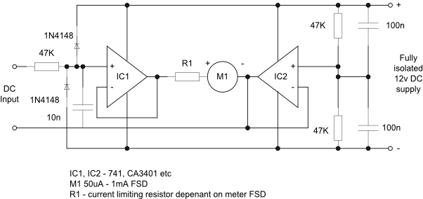
The power consumption is sufficiently low to permit battery operation but an on-off switch should be provided and this may be ganged to the wavemeter sensitivity control R2. A low consumption LED may be used as a power indicator - not shown.
As shown, both op-amps have a very low output impedance so R1 should be used to provide current limiting to prevent damage to the meter movement. Two 1N4148 diodes may be connected in parallel across the meter, one in the opposite direction to the other, to provide additional protection in combination with R1.
Low voltage low current op-amps would allow the DC supply to be reduced to 9v.
The overall sensitivity could be further improved by providing a small forward bias to the wavemeter OA90 diodes - the constructor is left to decide on this option.
Inductor L4 is made of 18swg tinned copper wire and is divided into two parts. L4a is two wires in parallel from the wafer to the body of the 150pF tuning capacitor and L4b is a hairpin loop of the same size wire. L4b is adjusted during calibration.
Resistor R1 ensures that the sensitivity cannot be reduced to zero and is typically about 2 - 5% of the value of R2 so set R1 = 220R and R2 = 10K.
The sensitivity and selectivity can be improved a little by the use of a unity gain op-amp buffer to drive the meter and reduce the loading on the tuned circuits although this is more effective on the lower frequency bands where the LC ratio progressively increases. In this case set R1 = 22K and R2 = 1Meg. Protect the op-amp input using a series resistor and diodes to the positive and negative rails. See below.