Valve Circuits 1
This page contains information on a number of prototype valve circuits. Please note that the use of dropper resistor R1 in the positive supply was for convenience in obtaining the required supply voltage for each circuit during the investigations. Users should arrange for the correct supply in each case to minimise the generation of heat and unnecessary use of energy. Most circuits for use in receivers do not require a 300V supply.
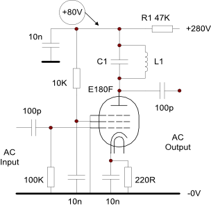
1. The first circuit shows an E180F pentode configured as a tuned amplifier at a test frequency of 13Mhz. C1 is 100pF and L1 is 10turns 26swg enamelled copper wire close wound on a 0.375inch diameter former with a dust iron tuning core.
The small signal voltage gain is x30 with the signal generator connected directly to the AC Input as shown. Resistor R1 is used for decoupling and also as as a voltage dropper as this valve is not designed to run on a 280V supply.
At 4V pk-
The E180F is a sharp cutoff valve and not suitable for AGC.

2. The second circuit shows an E180F pentode configured as a mixer with a test IF output of 13Mhz. C1 and L1 are as above. The small signal conversion gain is x10 with the signal generator connected directly to the AC Input as shown.
With the same valve connected as a triode the small signal conversion gain is x3. No sensitivity measurements were taken but the triode connected circuit should provide a lower equivalent noise resistance.
In both mixer examples the local oscillator (LO) input was 2V RMS at 37MHz and the RF Input was 50MHz. A tuned circuit would normally be used at the RF Input.
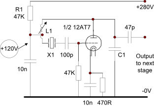
3. The circuit to the right is a Squier overtone oscillator. This is easy to get going and generates a high level into the following stage. However, there was audible evidence of random frequency wandering, probably due to excessive crystal heating, and it was also very sensitive to changes in the load presented by the following stage. Tests at 24.881Mhz used L1 with 22 turns tapped at 5 turns from the grid end and C1 not fitted. This circuit produced at least 600uA grid current in the following stage.
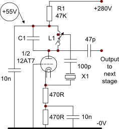
4. The next circuit offers a considerable improvement in frequency stability over the Squier, probably due to reduced dissipation in the crystal. Drive to the following stage was 500uA grid current or about 22V RMS and the oscillator anode current was higher.
L1 is 22 turns tapped at 5 turns from the cold end. The feedback may be reduced by moving the tap further towards the cold end if required. The circuit oscillated at 24.8793Mhz. No evidence of frequency wandering was noted. The semiconductor version of this circuit using a J310 FET also functions very well.
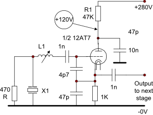
5. This circuit gave the best overall frequency stability compared to the above two oscillators but the output level was very much less at 500mV pk-
L1 and the series connected feedback capacitors plus the input capacitance of the valve form a quarter wave network that transforms the series resonance of the crystal X1 into a parallel resonant circuit. The semiconductor equivalent of this circuit using an NPN bipolar device also functions very well.
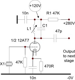
6. The circuit on the right is a classic tuned anode tuned grid oscillator which may be used with fundamental or overtone crystals and was used by Heathkit in many of their valve and solid state HF and VHF units.
The test crystal oscillated at 24.881Mhz and the circuit produced 600-
This circuit was also tested at 38.667Mhz with C1=10pF and L1 = 10 turns.
The following oscillator circuits were all tested using a 24.87917Mhz HC6/U third overtone crystal and others if stated. Oscillation frequency was monitored on a frequency counter and a local synthesised communications receiver. Output level was measured in the form of grid current in a following stage with a 47K grid resistor. L1 was wound on a former of 0.375 inch diameter with a dust iron core and using close wound 26swg enamelled copper wire.
It is recommended that the oscillator circuits should be run from a regulated HT supply .

8. The circuit on the right is a classic tuned anode amplifier using the EF183 vari-
Three sample valves were tested with an input signal level of 0.21v pk-
|
Condition |
Output level |
|
Signal to I/P 1 |
50v pk- |
|
Signal to I/P 2 |
0.68v pk- |
The maximum output before distortion became obvious was 80V pk-
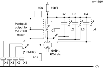
7. The circuit on the right is a variant of the classic tuned anode tuned grid oscillator in 6 above which was developed in order to provide push-
T1 resonates with C1 at 10.395MHz which is the band oscillator frequency for top band (1.5 -
On the higher frequency bands separate tuned circuits are used in parallel with the primary of T1. The band switch should have shorting contacts for all but the currently selected band to remove problems with stray resonances. Ony four of the twelve band positions are shown for simplicity.