I have received quite a few e-mails from people about replacing the S-Meter, Dial and MODE switch indicator bulbs.
The R1000 has three wire-ended 12V
bulbs, and the MODE indicator bulb is painted green! Your only choice here is
to buy a "clear" bulb and paint it green yourself - you can use the
spray paint used for Motor Car body repainting for this, because the paint will
not melt under the heat from the bulb.
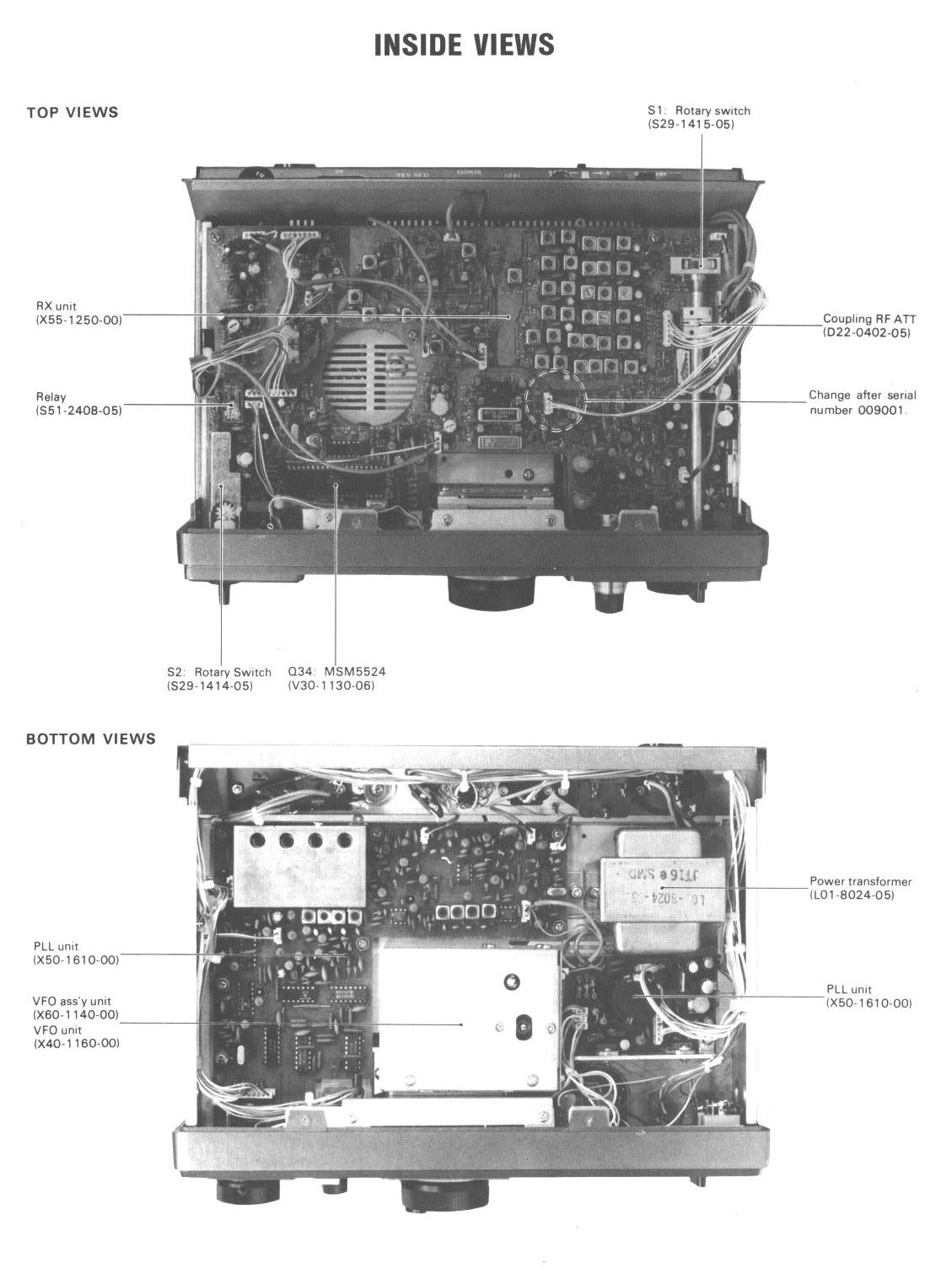
The indicator bulbs are wired back to a power supply sub-board on the right
of the PLL Unit, next to the Mains Transformer, which you can just see in the
"Inside Bottom View" jpeg on the website http://www.qsl.net/g0tud/R1000/inside.jpg.
The individual 2-pin connectors are marked as PL1, PL2 and PL3 they all connect
in parallel to the same 12 volt supply.
PIN 1 is +12v (via R209 22ohm 1W resistor) and PIN 2 is -ve end (goes to chassis
via R212 22ohm 1W resistor). You can make up your own twin lead/single pin versions
using any small push-on pin connectors, fitted with insulation sleeves. It is
possible to use the new high-brightness LED's now available via Maplin etc;
although each one will need to have its own appropriate value series resistor
for 12 volts - Anode to PIN 1 and Cathode to PIN 2.
Note - I have known R212 to overheat and go "open-circuit" due to
a failing Bulb (which went short circuit) - therefore neither of the remaining
bulbs would light up! The Radio would have shown signs of "overheating"
to begin with, smell of burning etc along with a hum in the loud speaker, as
it takes some time for R212 to eventually burn-out. The user being aware of
a "short" somewhere, suspecting the dial-lights, but not knowing about
PL1 - 3, would "snip" off each bulb in turn until the fault was cured!
The easiest way to re-fit new bulbs is to place a small rubber gromet (Maplin)
in to the original bulb mounting hole and push the "wire-ended" bulb
into the grommet. You may need to apply some araldite adhesive or similar to
fix in place. The wire tails of the bulbs will need to be "extended"
back to the power supply connectors etc, ensuring all wire joints are insulated
from each other and the metal work using "heat-shrink" sleeving etc.
This is not easy as the "route" the wires have to take requires some
dismantling of the PCB/Chassis components. For this reason I have not replaced
my SPREAD DIAL light as it means dismantling the VFO box - which is best left
alone!