Gardiner MMDS Downconverter LO2398
METEOSAT-7 modification
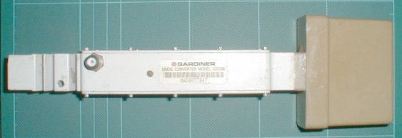
Fig.1 an unmodified Gardiner LO2398 Integrated MMDS Downconverter
Summary
This unit modifies to produce a METEOSAT-7 downconverter, with minimal additional parts. Please read the original 13cm article to get acquainted with the procedures involved. I am not duplicating this information in order to save space on qsl.net's servers.
Introduction
The modification is not necessarily more complex than that for the 13cm band. However there are a little more mechanics involved to produce the final result. This modification presumes that you have already followed the bulk of the 13cm article, removing the antenna feed and replacing it with an SMA socket, have removed the microcontroller, and tidied up the IF amplifier. The power LED is not fitted as suggested for reasons outlined further in this text.
Steps now involved are...
i) To align the Local Oscillator to a suitable frequency (in the author's case 2GHz)
ii) To modify the front end and filter PCB to improve response at 1.69GHz and remove the original 2.5GHz filter
iii) To install a new bandpass filter about 1.69GHz
iv) To add an additional MMIC amplifier in the front end chain to restore some gain
Once these have been done the unit is ready and very able to receive signals from METEOSAT's APT service on 1691MHz
Local Oscillator
We have to choose a suitable LO for the downconverter. The first limitation is that the PLL will not lock up successfully anywhere lower than around 1800MHz without extensive alteration. Your scribe chose an LO of 2GHz as it was previously used with the 13cm modification with comparitive ease, and was able to use a wideband multimode scanner for reception easily. However others may not be so well equipped, and therefore it's important to be able to choose alternatives.
A 144MHz IF is attainable in the authors opinion but has yet to be tested
A 432MHz IF is easily attainable, and would work well. Lack of suitable quartz has prevented this being tried
A 10MHz crystal locks the PLL at 2GHz with an extension to the VCO stripline. For locking a counter is desireable, but not mandatory. A voltage check on the VCO tune line can be carried out instead. Looking for a similar voltage to the original locked state at 2398MHz. The unlocked state is somewhat obvious on a DMM.
Once locked, there is ample injection to the mixer courtesy of the MMIC following the VCO. The mixer still performs well at 1691MHz which is gratifying.
Front End
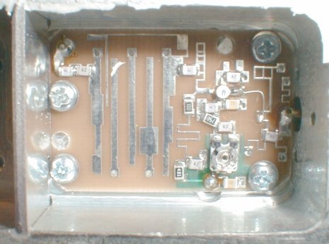
Fig. 2 - The unmodified front end PCB
The first stage GaAs front end needs some modification to receive well at 1691MHz. This is not as difficult as it would seem. A few tracks are cut, two capacitors removed and jumpered, and an additional capacitor is added. With access to sophisticated equipment, better results could no doubt be obtained. The result was, however sufficient to produce a good signal from both METEOSAT-7 itself, and the signal generator on the bench.
The stripline filter also needs to be removed to the state shown in the photograph. A scalpel cuts the tracks in the places shown to leave a short stripline coupling padto insert the MMIC and filter. Where not required, the original tracks are removed by application of a soldering iron to the extreme edge, and lifting the print with a pair of sharp ended tweezers. Following with the iron down the entire length to the base ground via and pulling the print away. Finally once free the print is cut from the ground via using a scalpel or sharp craft knife.
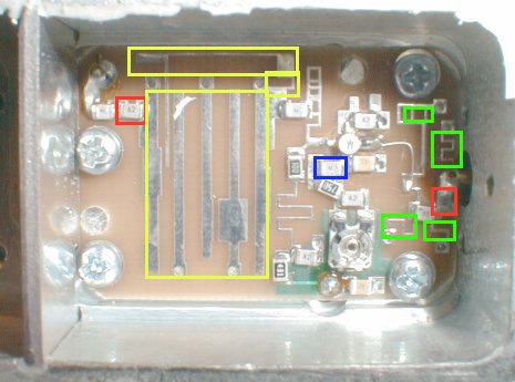
Fig. 3 - The work areas involved in the front end modification
The picture above illustrates the work areas on the front end. The capacitors outlined in RED are to be removed and the pads jumpered using a little tinned copper foil. The pcb traces in GREEN are to be removed. Note on the topmost inductor (top right near the screwhead) the only traces to be removed are within the green area. In the BLUE box, an extra 10pF chip capacitor is soldered in place on top of the existing one. In YELLOW, the stripline filter is removed completely, leaving only a small section of stripline into and out of the original circuitry, and the other inductor with the thinnest trace at the top of this picture is completely removed. The result should resemble the following picture...
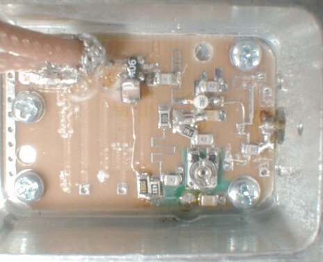
Fig. 4 - the modified front end ready for METEOSAT reception
This shows the additional MMIC stage. The two additional coax pigtails run to the outboard filter.
With this done, we can now insert the optional MMIC amplifier stage, and the bandpass filter.
Bandpasss filter
Insertion of the bandpass filter is the trickiest mechanical part of the conversion. There are available, cheaply, some LORCH microwave filters centred at 1675MHz with a 50MHz bandwidth, which are ideal for our purpose. The problem is that of the connectorised filter, The coax jumpers to and from the filter have to be persuaded to occupy the available space alongside the filter. There is just space available inside the downconverter casing to allow this to be done. You may have some SMA pigtails available - the more thin and flexible the cable the better. Semi rigid could be used if it is .085 diameter, but it is somewhat fraught, and will detatch from the PCB if mechanically shocked, causing some serious PCB damage .The filter will need to be mechanically anchored to accomplish this. Fortunately some 2-56 UNC holes exist in a couple of handy locations.
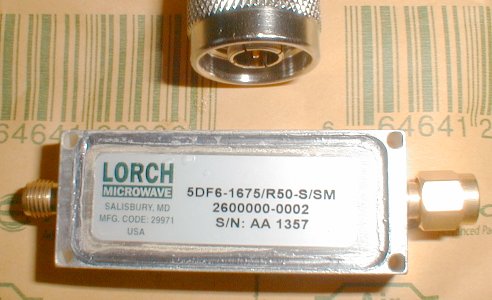
Fig.5 - Lorch bandpass filter for METEOSAT reception
Lorch microwave filter - Bandwidth is 50MHz centred at 1675MHz - ideal
If not, SMA connectors are available suitable for RG174 cable or similar. An SMA connector to the uninitiated is somewhat intimidating to put on due to it's size however.
Once the filter is installed, it is now possible to install the operation LED. Alternative wiring to that outlined on the original 13cm conversion is required, routing wires to alternative points via through holes in the casing. Well insulated wiring is required, for if the LED becomes detached and floats around in the casing there could be a short against the filter. It is, however possible to install an LED, perhaps a smaller SMD LED would be appropriate.
MMIC amplifier
Where the vacated stripline filter was originally, there is oppurtunity to add a MMIC amplifier. Some VAM-6 amplifiers were used as they had been removed previously from another project, but any MAR mmic of the MAR-6 series would do. A ground via is already available where the mmic is to have its ground leg soldered. Opening a small hole on the opposite side allows the other leg to be grounded also. Adding an RF choke onto the bias supply, a dropper resistor of 150R (1206 chip res) to the 8V supply line, and some nifty wiring using very thin silver plated wire taken from the braid of some scrap teflon coax completed the circuit. I used a 0603 chip capacitor of 10pF to bridge on to the filter from there.
The addition of the MMIC really does pull back some performance, and is quite worthwhile. I recommend it's addition...
Signals are receivable on the author's dish with only a little smooth noise. The largest problem now being the FM from METEOSAT now 'banging hard' against the walls of the IF filtering inside the scanner. As the PC and software have not yet been hooked up to the scanner, it is hard to judge whether this will have a great effect on the received pictures. Hopefully this will be updated when things are known for certain. In the meantime, good signals can be received, with the author's dish. A picture of this ex-inmarsat dish is shown below.
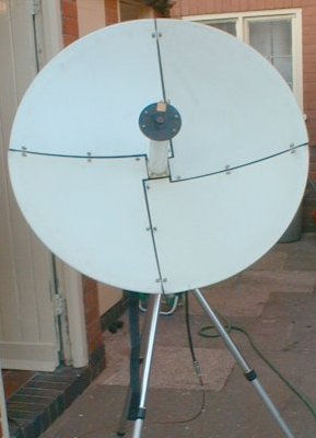
Fig.6 - The authors INMARSAT dish
A.M G0ORY - 05/10/02
back to the microwave radio page