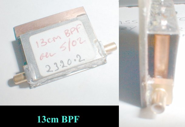
13cm 3 pole bandpass filter
This filter is easily made, if only a little fiddly due to the small dimensions. You will need some scrap lengths of UT-141 semi-rigid cable to make this filter and a piece a tinplate or sheet brass some 28.73 x 33.7mm. Construction is fairly simple, cut the lengths of semi-rigid outer to 17.74mm leaving at least 8-10mm of exposed inner per resonator, over the length of the resonator itself, to allow for soldering and tuning. Once these are done. Ensure you can push the inner of the coax into and out of the resonator body with only little limiting force. Remove the inner and spray with a light silicone grease to facilitate this, or alternatively carefully bore out the inner of the resonator with a 1mm drill. Do not bend the centre conductor!
Cut the carrier from a sheet of tinplate 28.73 x 33.7mm. Follow the drawing, and scribe the 7.1mm fold lines with a sharp knife to facilitate a smooth 90 degree bend. Don't bend them up yet though. mark the drill holes on the carrier, centering the three holes 9.93mm apart on the 28.73mm face both dimensions on that face. Drill the holes, ensuring that the UT-141 will be a push fit into the carrier, but not so tight as to cause buckling of the carrier itself. Use a smaller drill and open out with a taper reamer if necessary. The other side is to just clear the inner conductor, this can be a 1mm bit. Remove burrs, especially if working with tinplate - it's better to ensure the burrs will end up on the outside rather than the inside of the carrier.
Fold the carrier into the required U shape.
Solder the three resonators in place, ensuring the bottom of the resonator is flush with the outside wall of the carrier, and not jutting out. It is best to keep the inner conductors in at this stage and use them to prop up each resonator in the carrier. Work from left to right, or right to left as your preference.
Once all the resonators have been soldered in. Place the carrier onto the 005 board, or a piece of scrap pcb cut to size. The coupling wires to the filter are to coincide at 3.55mm from the earth end of the input and output resonators. Short L shaped silver plated wires will be ideal for this. Alternatively a solder-in smb socket is placed at exactly the right position for mounting straight to the carrier and the resonators!
Tuneup is fairly straightforward. It is necessary to keep a slight downward force on all three inner conductors to ensure good contact, otherwise the tuning jumps, and you could end up chasing your tail. You can first bring all three to approximate resonance which helps somewhat. Bring the resonators to resonance one at a time. Small pliers can pull the wire into and out of the filter. Use a wavemeter or other suitable indicator, and when happy with the position solder them one at a time. once done, crop the leads off and the filter is complete.
If by some unfortunate circumstance the tuning is not right. Desolder the wires, pull them all out, and start again. I have yet to see one that didn't tune right first time. Tuning is somewhat sharp, but has a smooth feel to it and is predictable.
This filter could also be scaled to other frequencies quite easily. And this filter will tune over more than just the 13cm Amateur allocation.

Here is the swept trace from the bandpass filter (in fact the trace shows the response through the entire assembly). The detector is a negative type, so the 'peak' is in the downwards direction. In the centre of the peak is 2320MHz. Half way up on either side of the peak is at around plus or minus 10MHz. I guess this is the 3dB point for the filter, but that will be confirmed by using a power meter and manually stepping the sweep instead
A.M 22/07/02 (rev 04/03)
Back to the 13cm microwave radio page