70 Mhz 4m LFA [Loop Fed
Array]
(Also 70cm LFA see bottom of page)
To begin with I think this has been my favourite, single band,
directional antenna. Not necessarily for the reasons you might
think. In terms of my favourite 70 mhz antenna of all it has to be
the Double Turnstile: some
horizontal gain in all directions (except vertical and horizontal
- it has to come from somewhere), no rotator required and
bandwidth to burn; I can see why GB3BUX does so well on 70mhz with
the same. However with the LFA I found it had more gain (albeit in
one direction) and importantly a wide bandwidth due to its full
wave loop. So it all depends what you need I guess. I like the
structural integrity of the LFA also. My thanks go to G0KSC for providing
the design and
allowing use for amateur non-commercial puposes. What follows is
simply my interpretation of another person's inspired idea. It
works. Interestingly I also scaled the same antenna for 70cm
without using any computer, and it worked fine too - yes 3
elements is not very much for 70cm, but it is compact.
The basic construction idea.
Waste not want not. I had a Double Turnstile which I constructed
and used for a couple of years. It was solid in performance. But,
you know how it goes, I decided a little more gain would be nice
to the South-East, as I have a good take off in that direction...
and I had not built an antenna for a while.. there was a buzz
about the LFA...
I reckoned I had all the materials so it should not cost me very
much. So I got to work. First I dismantled the Double Turnstile.
It was constructed from 1.25" tube and four 70mhz dipoles. The
tube was long enough to form the boom for a 3 element LFA and the
dipoles had enough aluminium (more or less) to form the Reflector,
Director and Loop of an LFA. I have always been a big fan of
folded dipoles in Yagi design. Very stable, mechanically strong
and simple self-matching design. So when I saw the photographs of
LFA it reminded me of an old Japanese folded dipole Yagi which I
still have - Maspro
10 element 2m yagi. As well as many old school UHF TV
Antenna driven elements made from flattened aluminium. In both of
these it was the mechanical strength I liked.
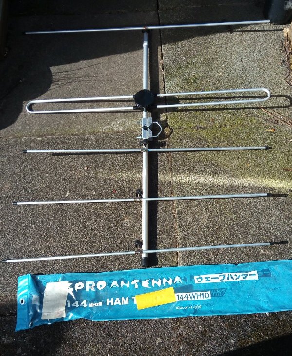
Note the horizontal (in plane) folded dipole
In the Maspro (bought in 1995) the dipole was in the horizontal
plane and (I always thought) stronger and less liable to wind load
than the traditional folded dipole. Of course the LFA is based
around a rectangular loop, but I thought it had similar benefits.
I have other yagis which match with gamma/delta or whatever, but I
always find these matching systems the weak point of the antenna.
Water and wind will find a way to cause issues over time. The coax
of the LFA is fixed directly to the element which is easy to seal.
Win/win. If the antenna is any good that is - which it is! This
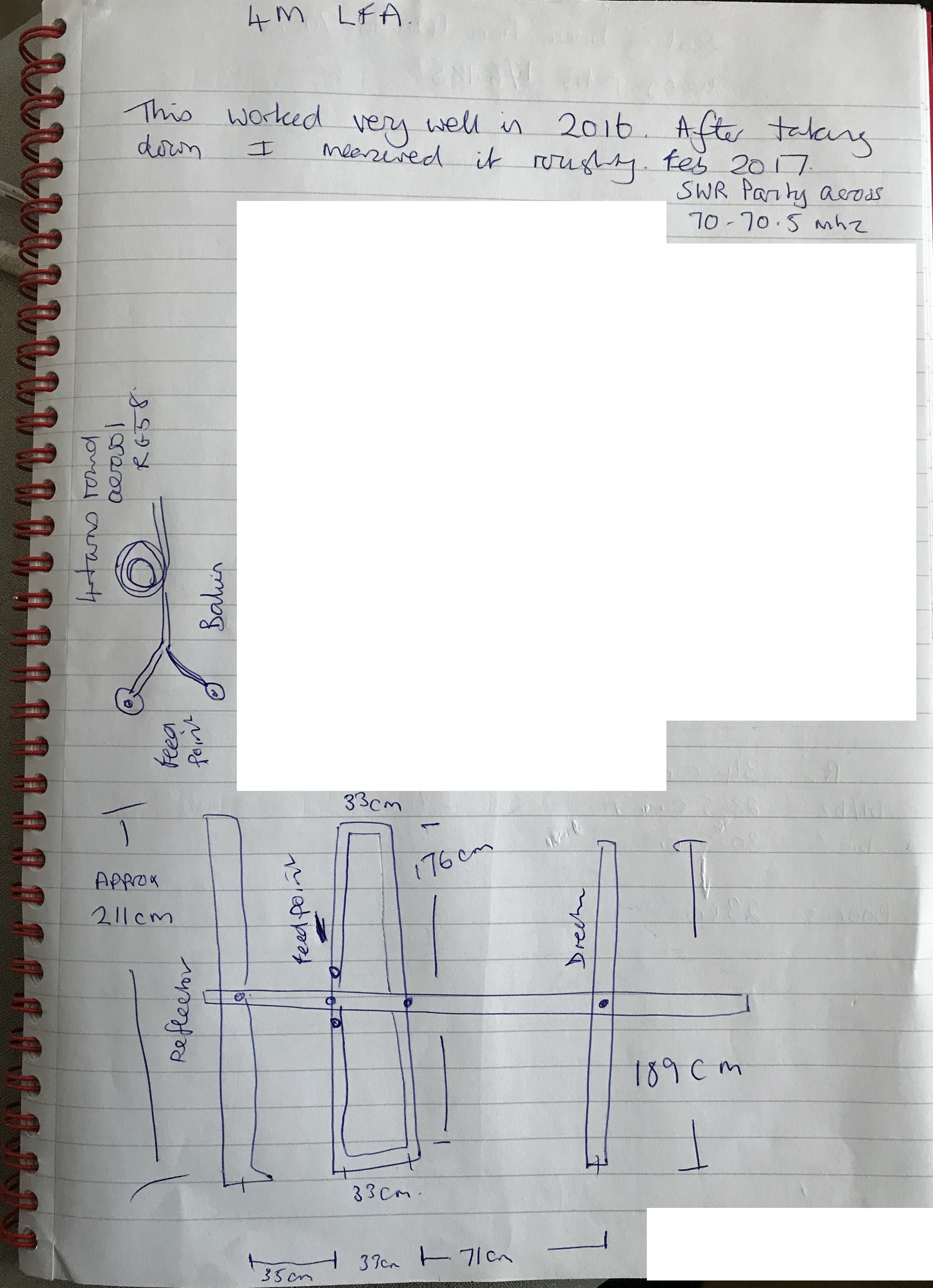
page is based upon my notes seen below. I made these after taking
the antenna down as I cannot find the original dimensions:
The measurements.
I had some problem in tracking these down. I read all of the
information on the website which talks of tolerances of a mm etc.
This put me off a little to begin with. Here was I with only scrap
materials. It needn't have. The finished antenna (once tuned - see
below) worked exceptionally well. Perhaps (I do not know) there
could be further gain with more precision and better quality of
materials, whatever, it out performed my 3 element commercial yagi
even so. Now the measurements below are those as I found on the
antenna when I took it down - for a further antenna test (see
DK7ZB below).
Reflector 211cm
Director 189 cm
Driven 'loop' is: 176cm across by 33cm centre wide. (I had this
way too wide to begin with and the SWR was very flat at 2:1) Later
when I made it smaller the SWR achieved virtual 1:1. It was my eye
expecting the traditional Reflector/Driven/Director to fall down
in width gradually. The width of the driven loop is less than the
director, as can be seen in the photgraph below. 176cm worked very
well.
I will add a diagram below in time...
Construction
This is where a centre line along the full length of the boom is
worthwhile getting correct. You do not want the elements as they
attach to the boom to be out of plane with each other - doubtless
why commercial versions use square boom. I find it very worthwhile
to scribe/mark a line on the top and the bottom of the boom for
the full length so that when I drill through for the dipole
centres (I used 4 of these, more later) I drill from the centre
line at the top and emerge out from the centre line below. This
keeps each dipole centre square to the boom and in the same plane
as the others.
I used the following dimensions: 35 cm from the centre of the
reflector to the centre of the feed point dipole centre. 33 cm to
the next dipole centre (which makes up the parallel section of the
loop). 71cm to the director dipole centre.
The method employed was to drill through the boom. Attach dipole
centres at four points. Only one of these was actually used for
coax (via a coaxial coil balun) at the feedpoint of the driven
element. The other 3 were simply bridged internally, using
insulated wire as thick as would fit the dipole centre terminals.
Once the half elements are attached the short makes them one
single element, isolated from the boom. The use of the same dipole
centre throughout keeps all of the elements the same distance from
the boom.
The loop section was achieved with smaller diameter aluminium at
the ends which slide inside the two loop elements to create the
rectangle - trombone style. These slide in and out also to adjust
SWR and clamp into postion. In my case a width of 176cm appeared
optimum. The dipole centre nearest the reflector is the coax
feedpoint, the other is bridged internally as above.
Balun.
The balun is ths simplest part of the whole design. I attached
eyes to the end of the feed coax. These fitted inside the
feedpoint dipole centre and were bolted into place withing a
dipole centre, then sealed by the dipole centre cap (along with
plenty of self-amalgamating
tape 25mm wide, worth its weight in gold for any antenna
builder, as well as liquid
tape on the inner screws inside of the dipole centre). The
coax behind this I wound four times around a standard aerosol can
then secured with cable ties (zip ties) and removed the can
leaving a loop in the coax which I fixed (cable ties again) to the
boom. The farther end of the coax went to the shack. After tuning
the coax was attached to the mast with cable ties. No joints, no
chance of leaks - this is why I love the LFA.
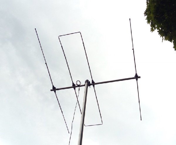
See balun on top
SWR
As stated above at first I had the loop way too wide. I set it by
eye to look like the classic yagi 'Xmas tree' profile. This is
wrong. I eventually found the SWR was great at about 60mhz! It was
then I realised my mistake and slid the loop ends further in until
1:1 (as far as the mass of the needle of my SWR meter was
concerned anyway) was achieved. This antenna was up all summer and
the following winter. It worked an absolute treat and will take
whatever power you care to put through it. I only replaced it
because I had need of 6m/4m/2m and I have only one pole. This was where the DK7ZB came
in...
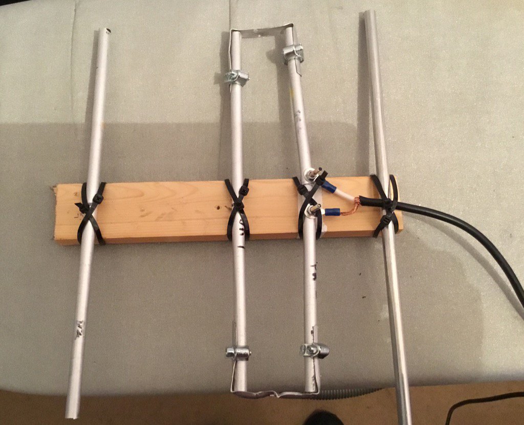
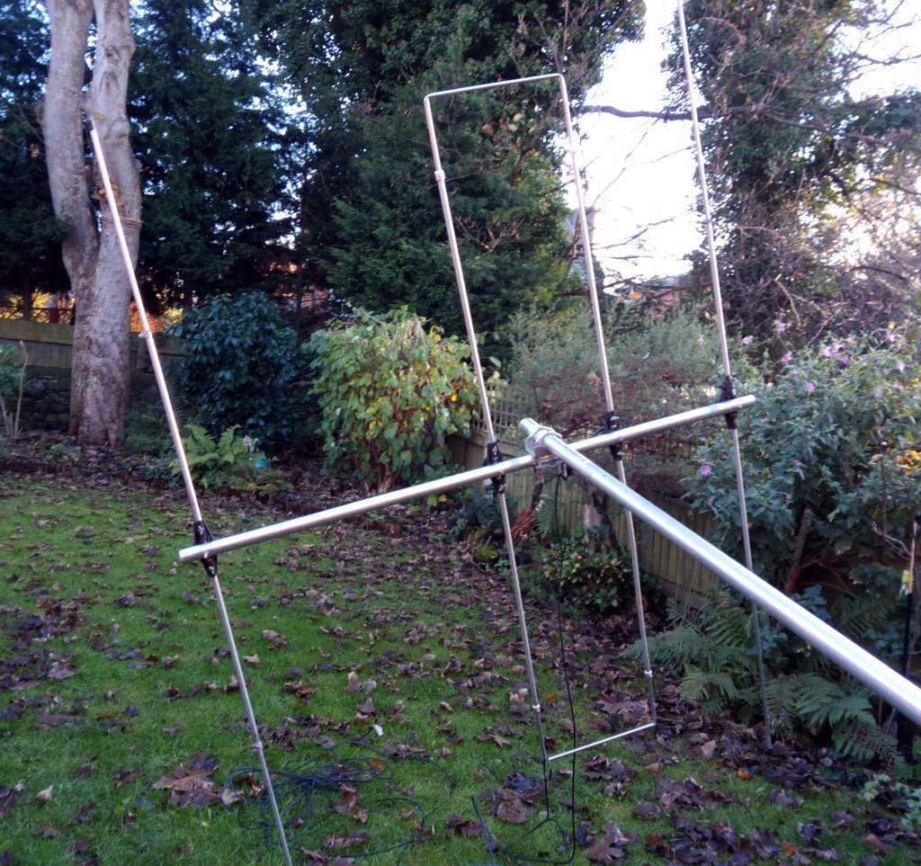
First Testing (Photograph)
Note the 4 dipole centre construction technique. Three of the
centres are shorted internally apart from the coax feedpoint
closest to the reflector - take care to keep these 'shorts'
isolated from the bolts which hold the diploe centre to the boom,
I just used insulated 20 amp wire. The coax coil balun is obscured
by the pole - it is simply cable tied above the boom, see above.
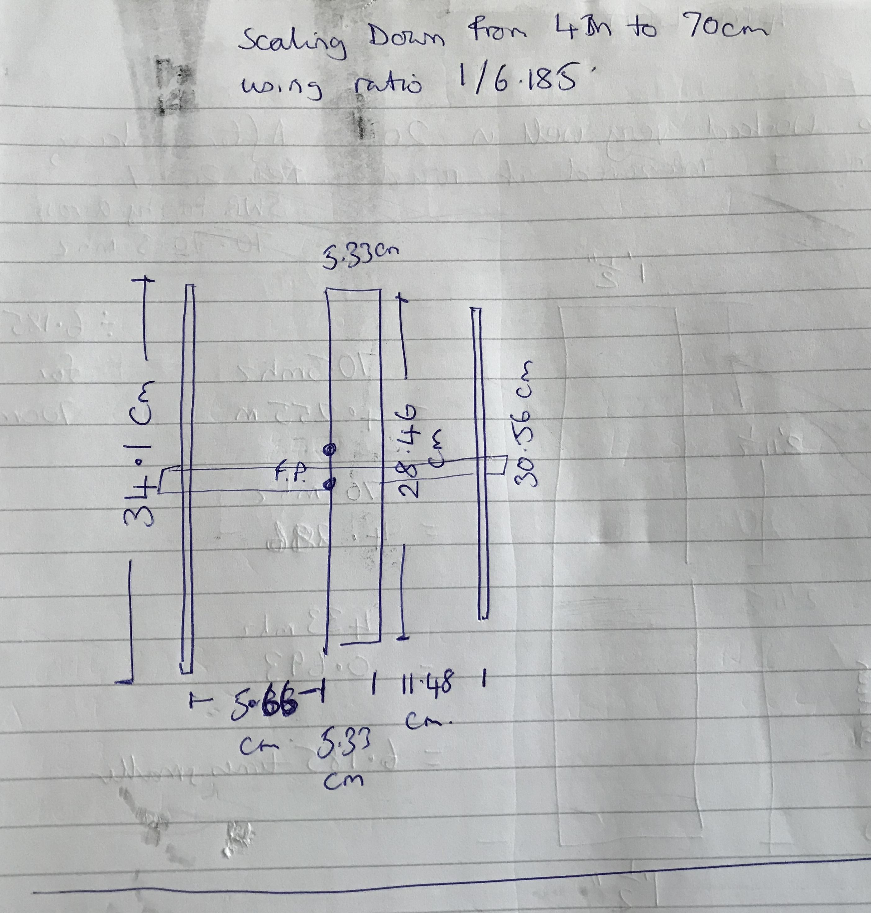
70CM
LFA
Just for fun I scaled down the antenna by 1/6.185 to produce
the antenna below - sans balun. It works. How well I cannot
tell as I only tried it indoors. However it demonstrated the
same flat SWR over a wide frequency range.
Home