<%@ Language=JavaScript %>
G0ISW HF/VHF/UHF Station
My name is
Philip
and since 1985 I have held a
UK Government license for
experimental Radio Communications, having qualified by passing City & Guilds technical/theory
examinations and a 12 WPM Morse
Code
transmitting and receiving test. I hold the Advanced Full license Amateur Radio call sign:
G0ISW
spoken phonetically as
'Golf Zero India Sierra Whisky' and shown below in Morse Code.
--. ----- .. ... .--
If you cannot see the full
index shown on the left edge of your screen, please go to my main page at
I
live in the historical old town of
Penrith, in the County of Cumbria (Maidenhead locator IO84OQ)on the edge of the
Lake District National Park'
in NW
England, from where the majority of my Amateur
Radio operation takes place. My 2013 QSL card design above shows 'Ullswater
lake' which I can see from my house, the town centre of 'Penrith' where I live
and my main radio for many years was a Kenwood TS-2000
HF/VHF/UHF transceiver.
I have been a Radio Amateur since 1985
and used HF/VHF/UHF radios professionally before then.
Summary
of Locator squares worked by G0ISW on VHF/UHF bands all terrestrial
Whilst my main interest within
Amateur Radio has always been VHF DX, I still enjoy working stations on HF
around the World with my modest equipment and covert antennas, the latter
being due to living in a Conservation area where visible external aerials
are not permitted. There are currently 340 DXCC Countries to work and my
total to date is
DXCC 178
Countries worked
There are lots of mountains and lakes
here, the area is very rural with a low population and few Radio Amateurs. it is
classed as 'an area of outstanding natural beauty' and has had protected
'National Park' status since 1951, making it a popular tourism destination.
My main interest since becoming a
Radio Amateur in 1985 remains experimenting with VHF propagation,
collecting Maidenhead Grid squares and trying new data modes. My primary
radio from 2001 to 2019 was a
Kenwood TS-2000,
however from late June 2019 I have been using an
Icom IC-7300 for
50/70 MHz and
an Icom-7100
for HF/144/432 MHz
From
April to September
I will be found chasing VHF DX locator squares/Countries via
Sporadic-E
propagation on the
50 MHz
and
70 MHz
bands. On
50 MHz I most often listen on:
50.313 MHz
- FT8
using
WSJT, JT-Alert
and WSJT-X
software.
In 2009 I last moved house and now live in a
'Conservation area' in Penrith that means no visible external aerials
are permitted,
therefore all the masts, rotators and beam antennas I used before have had
to be replaced by much less efficient and smaller aerials that I can hide
from view near ground level.
Despite these restrictions I have had
good results in June/July 2013 working across Europe. My antennas were
Watson HALO loops until
25th July 2013 and then
PAR OA-50 and
OA-144 loops until
2019.
I now use vertical collinears for VHF/UHF only.
I have also been pleasantly surprised
by my Meteor Scatter success on 50 MHz
with such a modest antenna setup. During the
August 2013
Perseids Meteor
Shower there were plenty of stations active on
50.230 MHz using
JT6M mode and I worked with ease
Portugal and Spain.
I have since worked
Scotland, Guernsey, Germany, Sardinia
and Sweden
by Meteor Scatter on 50 MHz
with this modest antenna setup.
Interestingly on
12th August 2013 at
0744 UTC I also worked EI9E/P
in IO55VD square,
350 km away from
me so too close for easy Meteor Scatter. I heard many very brief MS pings
from this station but couldn't work him randomly. I then noticed some longer
none MS reflections that were random and not Troposcatter, using AirScout
software by DL2ALF
I was able to observe that all these longer 15-30 second reflections were
actually via
Aircraft Scatter (ACS)
propagation with planes flying over the Irish Sea crossing the path between
our two stations.
Looking for a really good flight path
I then worked
EI9E/P with ease, see
screen shot below. Notice the pink coloured mutual scatter zone and the pink
coloured aircraft that allowed us the QSO, the metallic body of this plane
being an excellent reflector even at 50 MHz. I took the screen shot after
the QSO was nearly complete so the aircraft had travelled slightly over the
path line. Had I clicked on the aircraft icon i would have known what the
flight and aircraft type was.
From September to April I can be
found operating on HF primarily using the FT8
data mode.
Again the antenna restrictions for my
house mean that I have to use a British Army tactical dipole at only 2m AGL
hidden on the boundary wooden fence top, yet I can still
work the World.
I had intended to operate QRP HF/50 MHz
portable in the UK, or abroad, using an
Elecraft KX3, miracle whip or
military tactical HF dipole, however due to work commitments this never
happened so my
KX-3
has now gone to someone who will actually use it. I still
have my Yaesu
FT-817
though.
G0ISW
HF / VHF/ UHF Recent Activity
For the very latest G0ISW news please
visit my new Amateur Radio Weblog below
My amateur radio
activity varies considerably by the time of year, but my favourite pastime
has always been and remains chasing VHF DX by Sporadic-E or
Meteor Scatter propagation on my favourite
50 MHz, 70 MHz and 144 MHz
bands.
Each April to
September I
will prioritise working VHF DX via Sporadic-E propagation, which is often a
daily occurrence on 50 MHz and peaking for
144 MHz with just a couple of days in June,
with the exact dates varying each year. The excitement of not knowing when
these extraordinary propagation openings will occur, or where to, remains
great fun. In particular I like chasing new Maidenhead locator squares or
Countries.
Below
map of 50 MHz European Sporadic-E locator
squares worked
During the Solar
maximum the F2 layer can be open with 50
MHz worldwide propagation between October to December from the UK. This occurred last time
for me back in 2001 and was a wonderful event with the
50 MHz band even open from the UK to Australia.
During the June Summer 2013
Sporadic-E season I had just started using
JT9-1
weak signal data mode and WSJT-X software on 50.293 MHz USB and
had been working stations around Europe again, with always the possibility
of working the USA via triple hop Es.
My days of chasing DX via Meteor Scatter are
probably over, although I still
experiment with a much inferior antenna system.
I will see what I can work with my ground based antennas, results via
Sporadic-E have been so encouraging that just maybe MS might still work.
Until late 2022 I continued to operate
often on
either HF
/ 50 MHz / 144 MHz / 432 MHz
from my 4x4 vehicle as G0ISW/M using a
Yaesu ATAS-120A antenna for
HF/50 MHz and a separate large Comet
50/144/432 MHz colinear.
I would have liked to
significantly improve my 50 MHz / 144MHz /432 MHz mobile SSB long distance
capability and get away from using short vertically polarised antennas.
Having had great success from home with my recently installed HALO (HAlf
wave LOop) antennas, they would be an obvious choice for mobile use too.
I found by chance the
design shown below by Mike Fedler N6TWW, which would be awesome if only I could
have replicated it.
I also vaguely recall
a commercial 144 MHz (2m) HALO loop design for
mobile use many years ago that had a PL259 base, support column and topped
with a circular wire loop section that could be fixed either horizontally or
vertically quickly, was it made by Palstar or
similar name?
I monitor my
local 2 metre repeater GB3EV on
145.700 MHz
FM and/or simplex 145.500 MHz FM when out walking.
I have also operated from
home with AX-25 Packet digipeating across Europe on
145.825 MHz
FM through Low Earth orbiting satellites or the International Space Station
(ISS)
G0ISW
HF / VHF/ UHF Radio shack
2009-Present day
G0ISW
HF / VHF/ UHF Radio shack
2005-2009
(Interactive photo use
your cursor to identify equipment IE only)
FT
G0ISW HF / VHF / UHF
Antennas
2005-2009
(Interactive photo,
use your cursor to identify equipment IE only)
Summary
of Locator squares worked by G0ISW on VHF/UHF bands all terrestrial
RSGB 50 MHz Countries award (10 Countries
2-way)(60 worked total)
VHF
RSGB 50 MHz DX Certificate (25 Countries)(60 worked
total)
VHF
RSGB 50 MHz Squares Award (25 Squares
required)(250 worked
total)
VHF
WAB Winter Award 1986-1987 (250 stations - All 144 MHz SSB)
VHF
SOTA Chaser 500 points Award (All 144 MHz FM)
VHF
SOTA Chaser 1000 points Award (All 144 MHz FM)
VHF
ANDE Satellite Deorbit Award
VHF
ARRL VUCC Award 50 MHz (100 Squares)
VHF
ARRL VUCC Award 144 MHz (100 Squares)
HF
European Phase Shift Keying Club
EUSPA 100 Award (100 European Stations PSK
Award)
HF
European Phase Shift Keying Club
EUSPA 200 Award (200 European Stations PSK
Award)
HF
European Phase Shift Keying Club PHPA
100 Award
(100 prefixes World
Wide using PSK modes)
HF
European Phase Shift Keying Club PHPA
200 Award (200 prefixes World
Wide using PSK modes)
HF
European Phase Shift Keying Club MGSPA 100 Award (100
Maidenhead Grid Squares using PSK)
HF/VHF
RSGB 75 years Award (Worked required number of stations in RSGB
75th Anniversary year)
HF/VHF
eDX 25 Countries (Worked over 25 different Countries verified
by eQSL.cc)
HF/VHF
DXCC (100
Countries worked World Wide)
HF/VHF
WAB Century Award (Worked 100 different WAB Book holders)
In 2006 I
finally achieved the SOTA Chaser ultimate award, the 'Shack Sloth', for
collecting 1000 points entirely from the comfort of my shack on 144 MHz
FM. This took me 4
years of continuous effort, working mobile/portable stations primarily on
Lake District summits.
As a visitor to this website please, please
Sign my
Guest Book, as I spend a considerable amount of time maintaining this site. I really appreciate your positive comments,
suggestions etc.
Your Guest Book entries
greatly help to maintain my enthusiasm for continuing this task after 23
years!
I've had to create a
new Guest Book due to the old Lycos/Tripod service closing down on
01.04.2012.
G0ISW Station history and
background
1960's
During the late 1960's as a young boy I was
fascinated and influenced by watching the television series 'The Man from UNCLE'
and seeing them use
their pen radio communicators, calling
"Open 'Channel D'
Emergency Relay".
I decided that I wanted to have a cool way of
communicating using radio like them.
My favourite film,
made in 1968, is "Where
Eagles Dare", about an Allied Special
Forces/SOE WW2 mission, which contained even more radios and famous spoken
lines like "Broadsword calling Danny Boy" that increased my interest
further. Little did I realise then, how much this film would ultimately
influence me over the next 40 years!
The
screenshots above from the film 'Where Eagles Dare' are copyright of MGM and are
displayed with gratitude to the
film fan
website of which I am a registered member.
1970's
Whilst at a boarding Secondary Grammar School,
one of my class friends from Hong Kong brought back with him two 49 MHz
FM handheld radios, which we had great fun playing with, although the workable
range was only about 200 metres at best.
We also had at the school a Combined Cadet Force (CCF)
which you could join from the age of 13 onwards, with an Army and RAF section. The Army
CCF section was divided into Royal Signals or
Royal Engineers. When I was old enough to join, with my interest in radio
communication, the Royal Signals section was
the obvious choice!
We had 1950's era British Army radios for
our CCF use:
Wireless Set No.88
being a battery operated
Short
range infantry transceiver, covering four channels in the
38 - 42 MHz
range, FM, 0.25W. The transceiver and the large battery being about the same
size. Instead of wearing these in pouches on belts as originally designed, we fitted them
onto GS metal manpack frames instead.
Wireless Set No.31
being a battery operated
Short
range infantry manpack transceiver, 41 channels in the
40-48 MHz range, FM, 0.3W and
interoperable with the 88 sets, took a very large battery in the base.
WW2 era Field Telephones
used
on exercises between fixed positions, spent many hours digging slits into fields with a bayonet to lay the
required D10 telephone cable
1980's
After having left school and using various HF
and VHF radios professionally for several years, I still enjoyed radio communications as
much as ever and wanted more fun radio use as a hobby, outside of work, so I then followed
a path to obtaining my Amateur Radio Full licence as shown below:
Passed Radio Amateurs Examination and issued with
then 'VHF
only' licence
G1MOG
1987
Issued with 'Full'
HF licence
G0ISW
I was first licensed
as a Radio Amateur in 1985, with the call sign
G1MOG and my first ever QSO was with Chris
G4CLB using my brand new
Yaesu FT-2700R
transceiver on 433 MHz
FM.
When travelling back to my original home
town in the Lake District on leave from work, I was inspired
to get on amateur radio HF by the slow morse transmissions of Bill Delamere G3PER
(SK) from Heysham, who I would hear on the M6 motorway as I neared Cumbria, or
on the return journey stuck in traffic jams near Lancaster! My other morse
inspiration was
Winston G4PEF. I had never particularly enjoyed
using morse code, but these two gentlemen renewed my enthusiasm.
I joined the
Hillingdon Amateur Radio Club
(HARC), which used to meet at Hillingdon Golf clubhouse in West London. In
1987
I didn't tell anyone else from the club that I planned to sit the 12 WPM Morse
Code examination and turned up at the test centre at Watford one evening,
only to find two other club members there who also hadn't told anyone else
either! One was Bob and the other
Jack Davies G0ISY
(SK 2009).
The highlight of the evening was when
we prepared to listen to the examiner sending Morse Code for us to receive and
we all plugged our headphones into his homemade splitter box for us then to
accidentally pickup up perfectly 'Capital Radio'
on 95.8 MHz FM
simultaneously with the his sent Morse! Somehow Jack and I managed to pass the test
despite the QRM!
I was delighted to receive in
time for
Christmas 1987
my full HF licence personally chosen first choice callsign of
--. ----- .. ... .--
In the summer of
1988 I took an ex
Argentine military
Racal Syncal 30
(TRA931) (liberated from the Falkland Islands in
1982) HF manpack transceiver
1.8-30 MHz to the HARC clubhouse and we worked
stations in the USA on 14 MHz USB
with
20 W
and a 2.4M long whip aerial, whilst sat outside in the sunshine.
I didn't have the required 24 volt battery pack and wasn't going to pay
Racal a quoted £315 for a new one,
so I used two small 12v motorcycle batteries in series instead.
The biggest Amateur Radio pileup I
ever had was on HF when I was invited by Mark ZC4ML
and Steve ZC4ST to
operate their club station ZC4EPI
at the British Forces Episkopi Sovereign Base Area in Cyprus in
1993. From memory the club radio was a
Kenwood TS-950
and I had a fantastic evening in their company, thanks guys.
In
October 2006 I
reactivated my old G1MOG
callsign,
which I held from 1985-1987
when it was a VHF only callsign. It was then a full
license callsign and could be used on any Amateur Band. In
2012 I was advised at
license revalidation time that I can only hold one callsign again, so I have
reluctantly surrendered the
G1MOG license.and now only use
G0ISW.
I hope that one of my children might eventually take up this
callsign; in England it is an old tradition and belief by some that if a
black cat crosses your path, it will bring you Good Luck......Below is a
picture of my original QSL card and a more recent one.
G0ISW/M Mobile Station - Renault Megane Dynamique (2005-2011)
BANDS
USED
TRANSCEIVER/ANTENNAS/ACCESSORIES/COMMENTS
HF
(7-28Mhz)
2m
(144MHz)
70cm
(432MHz)
I have previously installed a
Yaesu FT-857D
in a Renault Megane Dynamique 1.9 DCI diesel car and found the radio to be a great little transceiver, full of
features including
illuminated buttons for night time driving.
The radio's memories are used mainly by me for storing
144 & 432 MHz FM repeaters and their CTCSS tones and scan very rapidly
when searching for activity.
This works very well, but I had to
additionally fit a
ferrite ring on the microphone lead to suppress alternator whine
pickup, which wasn't apparent when using the supplied hand microphone.
This position is perfect to see the display and to
reach the controls from the steering wheel.
I have set the Yaesu FT-857D
to display a different LCD colour for each operating band.
For HF and 50MHz I have installed a
Yaesu ATAS-120A
Active Tuning Antenna System screwdriver aerial, which allows simple
and quick band
changes from 7 - 50 MHz whilst on the move.
This
Yaesu ATAS-120A
is installed at the rear offside of my car, just above the bumper.
Extremely difficult
to see is my
separate micro
miniature magnetic mount 2m/70cm aerial
at the rear of the car on the roof.
You may just see in
this photograph a small red dot sticker, near the top of the
Yaesu ATAS-120A
aerial.
This visible red
dot is there so that from my rear view mirror when driving I can see
if the aerial has begun to unscrew from the SO-239 connector and stop the car before it can drop
off completely!
The
Yaesu ATAS-120A
is shown tuned to the correct height for the 14
MHz (20m) band.
Having a separate
2m/70cm aerial allows me to change from HF to
2m/70cm repeaters instantly,
without having to wait for the
Yaesu ATAS-120A
to tune.
I tend to work 2m/70cm repeaters until I
am in an area of no coverage and then change to HF.
I really struggled
to install any radio or aerial on my Renault Megane car.
The car roof is almost
entirely made from glass, having twin sunroofs, and a large HF triple magmount wouldn't stay
on the little remaining metalwork above the rear window.
The gap at the top
of the rear window and the car boot isn't wide enough to permit an aerial
mount to be installed there either. There are no
gutters as well.
Trying to get a
12 Volt power lead from the car battery
through the engine bulkhead was the most difficult problem.
Close-up view of my
Yaesu ATAS-120A
mounted at the rear of my car.
The stainless steel
'L' shaped mount was made for me by my friend Les, a friendly local metal worker, at SmallFab
here in Penrith, Cumbria and is
attached upside down to the car at the gap between the boot opening and the rear
bumper.
The 'L' shaped mount is bolted
to the metal bodywork, inside the boot behind where you can see the
number plate, and has sufficient grounding to
allow the
Yaesu ATAS-120A
to tune without problem.
There is no
noticeable vibration on the mount when driving and it is robust enough
not to bend or flex. It is about 1/8" or 4mm in thickness.
Also shown but not easily seen just
above the mount are the Yaesu ATAS-120 locking pins found
either side of the motor, at the base of the aerial, covered in a
layer of black electrical tape. This prevents them falling out through
vibration and then mechanical damage to the circuit board occurring.
This happened to me with a previous Yaesu
ATAS-100 aerial and is a simple preventative measure.
G0ISW/M Mobile Station - Jeep Wrangler Ultimate (2011-2022)
BANDS
USED
TRANSCEIVER/ANTENNAS/ACCESSORIES/COMMENTS
HF
(7-28Mhz)
2m
(144MHz)
70cm
(432MHz)
I have in June 2011 now installed my
Yaesu FT-857D
in a UK 2010 model Jeep Wrangler Ultimate (JK) 4 door, 2.8L diesel automatic car.
Very similar to the Jeep Wrangler Sahara Unlimited model.
I have remotely mounted the radio control head onto the top of the dash, using a
Waters & Stanton QS-200 metal removable air vent handheld radio mount, pushed into the vertical
air vents next to the windscreen and have bent the metal plate also
into the vertical position. I have bolted through the metal plate
onto the remote head bracket.
I also sawed off the end of the
QS-200 metal plate, which was above the remote radio control head. Using
this removable vent mount I can quickly remove the control head from
view for brief periods, whilst removing the entire radio from the
vehicle when parked for long periods.
This position is perfect to see the display and to
reach the controls from the steering wheel.
I have set the Yaesu FT-857D
to display a different LCD colour for each operating band.
For driver safety and operator
convenience I have again fitted a
Watson hands free microphone
to the sun visor and PTT
attached to the automatic gear change lever. I have since moved the
PTT higher up the selector lever than shown, as it was too low when
shifting down into fixed Gears 2 or 1.
Having the
PTT on the gear change lever is easy to operate and having hands
free operation is much safer to drive than using a fist microphone.
In the
picture you can also see the 12 Volt power lead I use to supply
power to my
Yaesu FT-857D.
Luckily this output is direct from the battery and is entirely
separate to the standard cigar socket and is rated at 13 Amps
maximum.
Using my
Yaesu FT-857D
at my usual less than 50 W output power, means I am drawing around
10 Amps maximum current and this socket is always powered on, even
with the ignition off.
I would not
be able to use this socket for any power level greater than 50 W.
For HF and 50MHz
I have installed my
Yaesu ATAS-120A
Active Tuning Antenna System screwdriver aerial, which allows simple
and quick band
changes from 7 - 50 MHz whilst on the move.
This
Yaesu ATAS-120A
is installed at the rear of my car, and is attached to the rear spare
tyre holder using purpose made brackets which simply bolt onto the
car using the existing bolts.
In this
picture, viewed from inside the rear Jeep Wrangler door, you can see
the
Yaesu ATAS-120A
antenna on the left and a
Watson W-770HB 144/432 MHz
(1/2 wave (2m) 2x5/8 wave 70cm)
colinear on the right (N.B. Silver coloured antenna shown in photo
has been replaced by a Black
Watson W-770HB). The coaxial cables come down to the bottom of
the door and into the inside fixed using cable ties.
The door
rubber seal is sufficiently large to allow this cable entry without
nipping and entering from below ensures no rain drips along the
cable inside the vehicle.
In this
close-up photo of the
Yaesu ATAS-120A
you can see two large white dot stickers, near the base of the
aerial.
The lowest visible
white
dot is there so that from my rear view mirror, when driving, I can see
if the aerial has begun to unscrew from the SO-239 connector and stop the car before it can drop
off completely! Just in case.
The
Yaesu ATAS-120A
is shown tuned to the correct height for the 50
MHz (6m) band and the highest
white dot is there so that as the antenna tunes for HF bands and
gets physically longer I can see the gap between the two dots
increasing and know it is working. This is a hangover from my days
operating a Yaesu ATAS-100 where sometimes the antenna wouldn't
move!
Having a separate
2m/70cm aerial allows me to change from HF to
2m/70cm repeaters instantly,
without having to wait for the
Yaesu ATAS-120A
to tune.
I tend to work 2m/70cm repeaters until I
am in an area of no coverage and then change to HF.
The rear
hardtop of the Jeep Wrangler Ultimate (JK) is fibreglass and
removable, as is the entire roof. All of the
Yaesu ATAS-120A
whip is above the roof level even when set at its shortest
50 MHz operation length.
The separate
144/432 MHz colinear, whilst partially lower than the top roof line, still
manages to perform well because it is almost entirely higher than the bulk of the
vehicle metal bodywork.
I have no
ignition or other electrical noise from the Jeep Wrangler Ultimate
with the exception of the 10 MHz (30m)
band. This does not cause me any trouble as I only operate voice
from the vehicle on the other bands. On the Jeep forums I have seen
lots of historical US comment about electrical ignition noise, but
maybe my UK model with its diesel engine is less of a problem, I
don't know, or maybe newer petrol engines are cured.
Close-up view of my
Yaesu ATAS-120A
mounted at the rear of my car.
The steel
'L' shaped mounts were made again for me by my friend Les, a friendly local metal worker, at SmallFab
here in Penrith, Cumbria and are
attached behind the rear spare wheel carrier, using the existing
bolts.
The 'L' shaped mounts
are bolted
to the metal bodywork, and have sufficient grounding to
allow the
Yaesu ATAS-120A
to tune without problem. The rear door opens with the antennas
attached.
Using a combination
of either simplex, repeaters or EchoLink I can cycle along and talk,
around the local area or around the World.
The metal rear
pannier mount provides a substantial ground to attach a 5/8 wave
2m &
2 x 5/8 wave 70cm aerial with plenty of gain.
You can see my
Kenwood TH-F7E
2m/70cm handheld attached using a bike handlebar belt clip mount and on the right a PTT/VOX unit originally
designed for a Kenwood PMR446 radio.
I can either use
the PTT pressed by my thumb whilst gripping the handlebars or use the
VOX function built into this radio or the PTT unit.
When wet weather is
anticipated I cover the
Kenwood TH-F7E
with a clear plastic bag and rubber band, which is a simple and
practical solution to keeping water out.
Attached to the
exterior of my cycling helmet is a Kenwood headset comprised of an on
the ear earpiece and boom microphone. This was originally designed for
a Kenwood PMR446 radio, but was found to be totally compatible and a
lot cheaper than the identical amateur radio model.
It is attached to
the helmet using tie grips placed through the air vent holes.
The headset
attaches to the Kenwood PTT/VOX unit with a 1m cable terminated with a
3.5mm plug fitting.
G0ISW/M (Pedestrian) Mobile Station
BANDS
USED
TRANSCEIVER
ANTENNAS/ACCESSORIES/COMMENTS
2m
(144MHz)
70cm
(432MHz)
My
Kenwood TH-F7E
is a
very versatile radio,
ideal for use on my local 2m repeater GB3EV
on 145.700 MHz and the lithium-ion battery
lasts all day.
I sold my first one
and had to buy a second one as I missed it so much!
G0ISW/P Portable (Holiday) Station - usually EA6/G0ISW
A very versatile
radio, used by me extensively on holiday and easily able to work
most of Europe on 5w SSB voice from the beach!
During previous
solar maximum years I have worked the USA and South America on
14 MHz just with the
Miracle Whip, indoors!
I
upgraded the battery pack by replacing it
with Ni-MH 2.3 Ah cells and making the 'green wire' modification so
that I can recharge them in situ.
I intend in
2011 to try to work APRS via the ISS and PCSAT (NO-44) satellites
using my FT-817 with UISS software and a RigExpert Tiny interface
from my usual holiday destination of Peurto Pollenca, Majorca in
JM19NV locator square.
What a battle I have had trying to
interface my Yaesu FT-817
with MixW software and my RigExpert Tiny interface.
Having looked everywhere on the
internet to try to obtain the correct CAT and soundcard settings I
have finally managed to get the Yaesu FT-817
to transmit PSK-31, but still haven't managed to get the MixW
software to show the frequency on the laptop display.
My MixW settings for the
Yaesu FT-817
with RigExpert Tiny interface are as follow:
Sound Device Settings
Device: Computer Soundcard
Input: Line (RigExpert Virtual
Sound)
Output: Speakers (Realtek High
Definition)
TRCVR CAT/PTT
CAT: Yaesu
Model: FT-817
PTT via CAT command: Ticked
AFSK in place of FSK: Ticked
DIG (Yaesu) is: USB
Default digi mode: DIG
Serial Port
Port: COM5 (This will vary
depending upon your own computer)
Baud rate: 38400
Data bits: 8
Parity: None
Stop bits: 1
RTS: PTT
DTR: CW
Yaesu FT-817 settings
CAT rate: 38400
Mode: DIG
G0ISW SSB / AM Station equipment
Microphones:
Noise Gate:
Equalizer:
Compressor:
Peak Limiter:
Mixer:
Power Supply:
Transceiver:
Amplifier:
Antenna Tuner:
Ant 3.5-28MHz:
Ant 3.5-28MHz:
Ant 50MHz:
Ant 144MHz:
Ant 432MHz:
Recording:
Audio Analysis:
Computer:
Operating system:
Radio interface:
Audio Hardware:
Keyboard:
Audio Reproduction:
Misc Hardware:
Behringer B-1
Studio Condenser microphone 20 Hz to 20 kHz
Adonis AM-308 Desk Top electret condenser microphone (modified
with internal switchable piptone generator for VHF use)
W2IHY iBOX (Matches levels from DEQ2496 to Kenwood TS-2000 DSP)
HP Standard PS/2 with USB adaptor
Sony MDR-XD200 Stereo
Headphones (10-22,000 Hz)
Samson SD-5 Desktop microphone stand (Primary use)
Heil
Sound PL2T Microphone Boom
Heil Sound foot
switch (PTT with W2IHY iBOX)
Adonis AM-308 Desk
Microphone (Secondary use)
You may be wondering why I used all of the Behringer audio
equipment? The answer is that I like to experiment with my transmitted
audio and had during the late 1990's listened with fascination to
broadcast quality voices of the 'eSSB audio
net' on 14.178 MHz from the USA. For a full
description of eSSB please refer to the
website of John NU9N where
all about 'eSSB' is explained.
I
restrict my transmitted audio to a maximum of 3 kHz, usually
2.7 kHz,
but I do like to experiment also off-air with the Behringer DEQ2496 to
see the full range of sound that it and the Behringer B-1 studio
microphone are capable of.
I
worked Bill W2ONV once on air myself, when I was in my car in the Republic
of Ireland, as
EI/G0ISW/M on the eSSB audio net frequency 14.178
MHz, he played back my transmitted audio across the Atlantic for
me to hear.
For further audio examples from radio amateurs around the World using
various TX audio bandwidths, please visit
John NU9N's website MP3 page here.
I had my
Kenwood TS-2000 transceiver for over 11 years and then I was troubled with a regular, but intermittent, main
display fault where the screen showing frequency and other information
suddenly goes blank and all the front panel controls become locked.
Often the only temporary cure has been to switch off the separate power
supply and then switch it back on.
Despite my
Kenwood TS-2000 radio being sent to an authorised service dealer they
had been unable to identify or repeat the problem. Finally I had found
by chance an alternative solution and purchased the Kenwood RC-2000
mobile controller remote head. Using this had allowed me to see my
display to tune again! I am utterly convinced the problem is caused by
the accessory socket connection to my computer in some way.
1995
Since 1995 when I moved to a more urban location,
I voluntarily restricted my base station transceiver output power, from my
license permitted
400 watts, to a
maximum of only 50
watts on all bands! This helps to prevent any
potential
TVI/EMC
problems and has still allowed me to work most of Europe on
VHF and the World on HF.
This power reduction saves energy too, as
400 watts equates to
roughly a single bar electric fire and
50 watts equates to a
typical halogen GU-10 spotlight bulb. On VHF
Meteorscatter
on both
50 MHz and
144 MHz I have often
sent comparable signals to fellow European stations, with
their their much more impressive antenna arrays and higher power, whereas I
have mostly used a small Create
Log Periodic 5130-1N
antenna for my Meteor Scatter work.
50
Watts Light bulb
My Kenwood TS-2000 Transceiver limited
to 50
Watts
2009
Please note that since March 2009,
my days of being able to easily chase HF/VHF DX (after 23 years) came to a
temporary end following another house move.
I now live in a conservation area, where
outdoor aerials are not permitted (if obvious) and the loft has already been converted,
both of which make it very difficult for me to install antennas and operate effectively.
I have therefore
dismantled and given away, to local radio amateurs, all of my previously
used large HF directional antennas, taken down my mast and rotator. I am now
mostly active near home either walking or in my car on 144/432 MHz
FM
using my local repeaters
GB3EV (145.700 MHz)
and
GB3CA (433.325 MHz).
However, I had in
August 2010 uncovered a closed section of loft
space.
I have removed a disused water header tank, which has given me just enough
room to potentially install indoors my
favourite
VHF/UHF
Create
Log Periodic 5130-1N
50-1300 MHz antenna, in a
fixed 130 degree
direction facing South-East
towards Continental Europe. Unfortunately I cannot rotate the antenna in this
space, but 95% of my previous QSO's have all been in this direction!
* Frequency
50-1300MHz * Elements 25 * Power 500W PEP * VSWR <2.0:1 * Forward gain
10-12dBi * Front-to-back ratio 15dB * Connector N-type * Wind survival
40m/sec * Boom length 3m * Mast size 38-50mm * Weight 5kg
Suitable for commercial and ham transmission and reception, these Log
Periodic antennas offer high gain over a wide frequency range.
This was the default direction my aerials
have always faced before, and my best contacts made, so
it should allow me to be on the air again on
50/144/432 MHz SSB and back again using my
favourite Meteor Scatter software WSJT,
after installation of a 10 metre length of
SSB-Ecoflex 10 low loss coaxial cable (Attenuation only
0.49dB at
144MHz) to be completed
when I get the time and inclination to do this.
I intended in
2010/2011
to experiment with the
Low Earth Orbiting satellites
on
145 MHz
uplink and
435 MHz FM downlinks using a portable Arrow
II antenna. Click on the images below for some YouTube video clips
demonstrating this antenna. K7AGE,
in particular, seems to have a wealth of experience and videos on this
subject.
From
May
2011 I am going to try again to work the AX25 Packet satellites such as
NO-44 PCSAT and the International Space Station on
145.825 MHz
FM using my
Kenwood
TS-2000
with UISS, AGWPE and Orbitron software.
I am also occasionally active on EchoLink
from home, node number
3116,
and now using my
Apple iPhone 3GS I am able to use
EchoLink from anywhere in the World, where I can get a
3G mobile phone signal or via Wi-Fi.
I am active from home on most HF bands
(3.5-28 MHz) with a small
Sandpiper
MV6+3 HF
vertical, used primarily for PSK31
data communications. My results have been mildly disappointing so far, due
to the low angle of radiation not being ideal for European and inter-G
working, which at this point in the Solar cycle is where most stations I
should be able to work are located.
This isn't
the fault of the
Sandpiper MV6+3 antenna, which I like, as I would have similar
results
with any omni directional vertical at this time and I have been spoiled
previously by having a rotatable HF beam with considerable gain at the last
house, so no comparison would be fair.
I have from
1st September 2010, installed a modern British Army
1.6-30MHz
Racal Military tactical adjustable wire dipole (Type 4011-900), at only
about 2.5m above ground level, on top of the garden fence, wall and in the
trees. It is green coloured, made from very flexible copper braid, Kevlar
strengthened and best of all is covert and cannot be seen by neighbours in
this conservation area.
I have
modified it slightly as I didn't have the matching Racal 'Centre Junction
Assembly'(4011-103-01) and have used instead an old amateur radio magnetic
balun, terminated with an SO-239 connector, and fed with 25 metres of 50 ohm
RG-58 coaxial cable.
Initial
testing has shown the
Racal Military tactical adjustable wire dipole to tune easily for a 1:1
SWR on all amateur bands between
3.5-28MHz,
using my
Kenwood TS-2000 internal ATU. Using
WSPR software very impressive results
have been made, with just 5 Watts low power, all over Europe and the Southern
UK. This is due to the high angles of radiation for this dipole compared to
low angles for the vertical.
VHF/UHF Tropo, Aurora & Sporadic-E
Between
1988-2008 I specialised in
VHF/UHF long distance (DX) communications on 50 MHz
and
144 MHz with Tropo, Aurora and Sporadic Es being my favourite
propagation modes, but having so many
mountains surrounding my QTH made it difficult for VHF/UHF radio
communications.
Shown below is a 3D aerial image
of my home location (QTH) at Penrith,
Cumbria, England (Locator IO84oq),
indicated by the white arrow, at
140 metres
above sea level, with higher ground surrounding all sides.
Despite the terrain I have been able to work stations thousands of km away and
have regularly been mentioned in both 'RadCom'
and
'Practical Wireless'
magazines for my
achievements in this field.
The map
below was created using Geog UK software by G4JNT.
The elevation contours are at 100m intervals and show the
high ground rising over 100m, immediately to the North-East of my QTH at a distance of
less than 2km
away, obstructing line of sight signals between
30-90 degrees.
At 20km
distance to the East
(Coloured RED) is
very high ground formed by
Cross Fell (893m / 2930ft),
Little Dun Fell (842m)
and Great Dunn Fell(848m /2782ft),
all obstructing my line of sight signals
between 70-90
degrees.
Below is a diagram which
shows the antenna elevations required for my aerials to pass obstructions caused
by hills around me. You can see that the best direction for me is
130
degrees and the worst is between
20-80 degrees.
When I lived in Ruislip in
West London, before
1990, I was able to make extensive use of
Tropo
Ducting to work stations on the Continent of Europe, indeed I could use
10W
on
432 MHz
USB
to work the stations of
HB9MIN/P
and
HB9AMH/P
in
JN37
square in Switzerland, using an ex Military flat phased array of 16 dipoles,
designed to work at military frequencies around
850 MHz.
I was also able to work Scandinavia on
144 MHz.
However since moving to the mountainous area of Penrith, Cumbria in
IO84
square all my attempts at working via
Tropo
Ducting have been defeated by having higher mountains blocking the path/duct
as I live near the valley floor.
To monitor the build-up of extensive and prolonged high air pressure needed to
establish a Tropo Ducting path, in the late
1980's
I had a chart recording brass
and wood Barograph made for me by Ron Lucking of Hampton Court, a retired watch
maker whom was also a Radio Amateur. I still use this fine Barograph today and
also have the latest in weather technology in the form of a wireless
Ventus W928 Meteotime weather station. I have discovered that I can use the
Ventus W928 weather station with
Weather-Display software
if the WD software is set to be used with an Irox weather station, as the Ventus
W928 is not listed as being supported.
50MHz yearly
propagation worked by G0ISW
Year
Month
Mode
DX/Comments
1987
June
Sporadic-E
Europe
ZC4VHF/5B4 / 9H1CG
1988
June to
August
Sporadic-E
Europe
1989
March
Aurora
Europe
May to
August
Sporadic-E
Europe
November to
December
F2
USA & South
America & West Indies & Africa WA1OUB / K8EFS / VE1YX / HC1BI Best ODX
(VP5D got away) (EL2FO Liberia got away)
1990
House Move - no activity
1991
June
Aurora
Europe
June to
July
Sporadic-E
Europe
1992
May to
September
Sporadic-E
Europe
1993
May to July
Sporadic-E
Europe
1994
February
Aurora
Scotland
May to
August
Sporadic-E
Europe /
JY7SIX & EA8/DJ3OS
1995
June to
July
Sporadic-E
Europe
1996-1999
House Move - left with no
external VHF aerials for DX
2000
May to
August
Sporadic E
Europe
2001
March
Aurora
Europe
June to
September
Sporadic-E
Europe
August
TEP+Es
Africa
- Reunion Island (FR1GZ heard calling CQ on 50.120 I didn't call him straight away, because
I thought it was France, by the time I realised he had gone!!!!)
October to
December
F2
Israel /
Lebanon/ Ghana / Cyprus / India (VU2ZAP got away!) / Canada / USA / Jordan
/ (Australia got away aaarghhh!)
2002
May to
August
Sporadic E
Europe
2003
May to
August
Sporadic E
Europe
(TF8GX got away!)
2004
May to July
Sporadic E
Europe
2005
May to June
Sporadic E
Europe
2006
June to
August
Sporadic E
Europe
2007
April to
August
Sporadic E
Europe
2008
May to
August
Sporadic E
Europe/
Sporadic E seems very poor this year!
2009
House Move - no activity
2010
May to
July
Sporadic E
Europe (No TX aerials)
2011
May to July
Sporadic E
Europe (No TX aerials)
2012
May to June
Sporadic E
Europe (No TX aerials) Where
are the F2 openings expected 11 years after 2001?
2013
May to August
Sporadic E
Europe (Halo & OA-50
loops for 6m)
2014
May to June
Sporadic E
Europe (OA-50 loop for 6m) - Very poor Es season indeed
2015
April to August
Sporadic E
Europe (OA-50 loop for 6/4/2m)
2016
April to August
Sporadic E
Europe
2017
May to September
Sporadic E
Europe
2018
May to August
Sporadic E
Europe (OA-50 loop for 6m &
Colinear for 4m/2m)
2019
May to August
Sporadic-E
Europe / Guadeloupe / USA (Quad band collinear
for 6m/4m/2m/70cm)
2020
April to December
Sporadic-E
Europe
2021
January to September
Sporadic-E
Europe / Africa / Cuba /
Guadeloupe
2022
June to August
Sporadic-E
Europe / Africa / Canada
2023
April to October
Sporadic-E
Europe (September and
October Es coincided with major MS showers)
May to August
TEP+Es
South Africa / Brazil /
Chile
2024
I consider my current Amateur Station to be average in
capabilities, but I have still managed to work on VHF very long distances to North Africa and the Black Sea coast on
144 MHz SSB, via
Sporadic Es, without a huge antenna system or any linear amplifier. Just
25
watts from a Yaesu FT-736R and a Create
Log Periodic 5130-1N aerial, which at
144 MHz
only has about 5dbi of gain and is equivalent to only a 4 element yagi!
For more local
144MHz FM simplex contacts the following two maps show the likely signal
strength and coverage, when I am using my Yaesu FT-8800 25W transceiver and an
Omni directional colinear aerial from home. This clearly shows I am very well
located for working SOTA or
WOTA stations on the Lake District hills.
Both maps created
using the fantastic
Mobile Radio software by
VE2DBE
Station AStation B
Amateur Radio Meteor Scatter
My favourite VHF propagation mode for
Amateur Radio use is
without doubt Meteor
Scatter. From
my IO84
Maidenhead locator square on
50 MHz and
144 MHz via
Meteor
Scatter, I used the
fantastic WSJT software
and the high speed FSK441 digital data mode.
The maximum practical range for
Meteor
Scatter
QSOs is
considered to be around 2300km,
with my best
distance being 1796km
to Estonia.
I have severe obstructions
to my signals when beaming between 20-80 degrees
due to nearby mountains.
Despite this almost
impossible direction for working anything at VHF/UHF I have managed to work
stations via Meteor
Scatter
as far afield as
Estonia
on 144MHz!
To get over both
hills my horizontal radiation lobe pattern needs to be at least 23 degrees above
the horizontal.
Interestingly experiments
in 2007 with SM7CMV on
50MHz where my radio signals were heard by him via
Meteor
Scattermany times, but I couldn't hear his signals despite my
station being much weaker in comparison, has resulted in me suggesting that
perhaps Knife Edge Diffraction followed by
Meteor
Scatter
allowed this apparent one-way flow? I know
Knife Edge Diffraction
occurs in that direction as I can work G stations in
IO94 square despite a clear
mountain obstruction of the Pennines.
Shown below is a
still image of my FSK441 QSO (using WSJT
software) with ES6RQ
on 21.12.2003 on 144.360 MHz
a distance of 1796km (1116 miles)
and
my best DX via Meteor
Scatter
so far. The burst captured below shows the signal I received from my friend
'Ants' in Estonia.
I was only using
50 watts
with my then Yaesu FT-847
transceiver and a 9 element Tonna Yagi at 150m asl to reply and you can see
my Meteor
Scatter
signal report received in Estonia of 27.
The date and time
shown on the captured screen above are not correct, as after the event I reran the recorded audio data so that I
could grab this image to present on this page.
Below is a
map of Stations I have worked on 144MHz
Meteor
Scatter. The maximum practical range for
Meteor
Scatter
QSOs is considered to be around
2200 km, with my best
distance so far being 1796 km.
I have managed to work stations via Meteor
Scatter
in
Iceland, France, Germany, Poland, Estonia, Czech Republic, Italy, Switzerland,
Croatia, Bosnia, Serbia, Slovenia, Norway, England, Holland, Denmark & Spain.
This came about because band conditions
were so
poor on HF and realistically I have worked as much as I can via the normal
VHF/UHF propagation modes. I am however finding it a very steep learning curve.
I now use
Orbitron satellite tracking software to alert
me in the shack, when the
Satellites are coming into range. I use
UISS software
to CAT
control my Kenwood TS-2000
radio and send the
AX-25 packet messages.
I use
AGW packet engine software
to
give me the ability to transmit and receive packet without a TNC using
my RigExpert standard interface. The
UISS software works in tandem with AGW and is a very useful tool for working
the ISS or digipeating through it. Within a day of downloading the software (on
Saturday 17th March 2006 at 1145UTC), and on my first attempt, I managed to have
my 145.990 MHz
FM packet signal digipeated by the
ISS (RS0ISS-3)
as
it flew overhead at 345km
altitude,
this was achieved using my normal VHF horizontal beam and using
25 watts.
See the image below, showing my QTH and
those of other successful Hams, displayed in
real-time, as heard by the ISS. The ISS position is shown and where it will
be in 5 minutes later (ISS-5).
In May 2011
I am only using an indoor 1/4 wave
144MHz
magnetic mount aerial, little bigger than a handheld radio aerial, as I have no
external antennas for 2 metres. I was pleasantly surprised today 23rd May 2011
to see that my
25W
145.825
MHz FM
AX-25 packet radio messages had been received onboard the ISS and retransmitted
(RS0ISS-4*)
as shown below in the text box, with the accompanying map image of active
stations.
20110523075625 :
ON4HF-9]U0TQW4,RS0ISS-4*,qAR,MM1PTT:`{]Z {yv/]"6I}www.on4hf.be=
20110523075623 : G0ISW]CQ,RS0ISS-4*,W3ADO-1,SGATE,WIDE,qAR,EI7IG:]IO84OQ/G
Pse send me ur # via SAT
20110523075618 : RS0ISS-4]CQ,SGATE,qAR,EI7IG:]ARISS - International
Space Station (BBS/APRS on)
Please do not attempt to connect to the
old International Space Station Packet BBS system, callsign RS0ISS-11, as you
will block the whole pass for all other European stations who can digipeat only
if the BBS is not being used. The BBS was established many years ago before the
advent of e-mail, the crew do not read it, and in order to obtain a QSL card
from the ISS you only have to now digipeat through it using the callsign
RS0ISS-4. The crew use e-mail, Facebook and Twitter, not the BBS.
Summary
of Locator squares worked via Satellites
International Space Station,
PCSAT (NO-44), ANDE-1
My best
Satellite DX on 145.825 MHz
FM Packet, via the Low
Earth Orbiting satellites above, is:
SV3EXT
in locator square KM18UA, a distance of 2720 km
UR3QLZ
in locator square KN77MT,
a distance of 2703 km
US5WDC
in locator square KN29BJ, a distance of 1918 km.
On 27th March 2012
when I worked
UR3QLZ via the ISS on
145.825 MHz FM packet, I was only using an indoor 1/2 wave 2m
collinear and 25 watts, no beam aerial here any more.
Historically, I realised that for consistent and reliable space
communications I should have upgraded my
antenna system, but I did not have the space for a high performance multiple
stacked 4x4 array, so it would have to be based upon a much simpler system. I noticed on the
GB4FUN amateur radio demonstration vehicle
that they have full satellite capability.
These aerials have a short
boom length less than 1.5m and can be mounted on the front of the mast, which is
particularly good for me as they would not catch on my HF beam mounted lower on my mast. The
quoted gain for the
2m X-Quad
is
10.5dBd and for the
70cm X-Quad
is
12.8dBd, which compare very
favourably with both a Tonna 9 element
144 MHz yagi at
13.1dBi and a Tonna 19
element
432 MHz yagi at
16.2dBi, but being only
horizontally polarised, about 3m long and not able to be mounted on the front of
the mast boom. Converting dBD to dBi suggests that the gain is almost the same.
Interestingly these antennas
can be configured for horizontal, vertical, Left or Right hand circular
polarisation (RHCP) the latter being the preferred
setup for satellite use and also EME. Using a WIMO phasing harness
for each antenna, further
simplifies setup.
As of January 2010 I intend to use
a modest portable Low Earth Orbiting (LEO) Satellite system based upon the
Arrow II Satellite Antenna
and my
Kenwood TH-F7
5W
144/432 MHz handheld.
There are very
few radio amateurs here in Penrith, or the surrounding area. The local Amateur
Radio club is the
Eden Valley
Amateur Radio Society (EVRS) which meets in Penrith, on the last
Thursday of each month at 19:30 hrs local time, in the
Royal British Legion club.
Visitors are very welcome.
Amateur radio activity is mostly to be found on the local
2m repeater GB3EV
on 145.700 MHz FM (CTCSS 77Hz)for fixed and
mobile stations due to the sparsity of activity and the mountains which
block simplex contacts between the valleys. This repeater is now connected
to the Internet by way of EchoLink Node 528770, which is a very welcome
addition.
Radios I have
owned and operated over the years
* denotes still in use
If
you already use your computer soundcard for data modes such as PSK31,
then
you can use WSPR (Distant Whispers) software
by K1JT, with
your existing hardware. The software transforms your station into an automated beacon and weak
signal reception hub.
You will be amazed how far your low power signals
can be heard and can see maps in real time. Great for antenna
experimentation and comparison too. There is even a searchable
WSPR spots database.
2010
Below is an
computer screen grab using
WSPR software and taken from the
WSPRnet pages
showing my 5 Watts QRP signals on
10MHz
on Friday 3rd September 2010. Comparing this with my HF vertical aerial I can
see immediately better results for working the nearby Continent, which is what
I would expect.
Using the
WSPRnet
website and its
'spot database query'
research tool, I can enter search parameters for callsign, band, number of
spots, and select the order they are displayed in such as timestamp, distance,
SNR, km per Watt etc.
In the
example below, dated from late 2010, I have selected 5 spots for my signals on the
10MHz
band and placed them in longest distance order. I can see that my best
distance so far is to
W3HH
at
6751km
and I can also see that all 5 spots were using my
Sandpiper MV6+3 HF vertical,
as I only put up my
Racal Military tactical adjustable wire dipole on 1st September 2010.
Using spot archive (no
automatic refresh). 5 spots:
Timestamp
Call
MHz
SNR
Drift
Grid
Pwr
Reporter
RGrid
km
az
2010-08-31 22:22
G0ISW
10.140199
-13
0
IO84oq
5
W3HH
EL89vb
6751
280
2009-07-23 21:32
G0ISW
10.140223
-26
0
IO84oq
5
K8CXM
EM79
6074
290
2009-07-23 21:10
G0ISW
10.140214
-25
0
IO84oq
5
W4JE
FM08qw
5724
285
2010-08-31 23:00
G0ISW
10.140193
-17
0
IO84oq
5
K8CT
EN83ce
5711
293
2009-07-23 21:32
G0ISW
10.140203
-25
0
IO84oq
5
K1JT
FN20
5383
284
Query time: 0.004 sec
However,
on
14 MHz
it is a different story, as I can see from the results shown below that my
two best distances were both on dates after 1st September 2010, when I was
using my
Racal Military tactical adjustable wire dipole. Obviously you have to take
into account the variations in propagation, but this software does allow
you to compare antenna system performance if tests are carried close in
time to
each other.
2011
In
April 2011, I have returned to using
my
Sandpiper MV6+3 HF vertical
as my primary aerial, as it will tune up on
50 MHz
for the Sporadic-E season in April-July, whereas my dipole won't.
Below is a map showing my QRP 5W
10MHz WSPR
signals reaching the USA using a
Sandpiper MV6+3 HF vertical on
the morning of 6th April 2011.
Below is a map showing my 5W
10MHz WSPR
signals reaching VK1UN
in Australia using my 2m tall
Sandpiper MV6+3 HF vertical on
8th April 2011.
The WSPRnet database shows my
10.140195 MHz signal to
VK1UN in Australia had a
SNR of -28 dB and
the distance was my best yet at 16947 km.
The WSPRnet database shows my best ever DX signals
have all occurred so far on the
10MHz band and I can
tell by the dates that all were achieved using my
Sandpiper MV6+3 HF vertical,
rather than my dipole. I would expect this due to the low angle of radiation
from the vertical aerial which is better suited for long distance (DX)
working.
Here below is my
10 MHz
signal being received on 16th April 2011 by the man himself K1JT, Joe
Taylor, the author of WSPR and WSJT software
On HF from home, my
preferred mode of operation in 2011 remains PSK31 data using
MixW software.
In October 2011 I have
started to look at other HF data modes and tried today
JT65-HF on
28 MHz
just to see what band conditions were like. Wow!
Shown below is a screenshot using
PSK Reporter
of stations heard by me on 28.076 MHz
(10m), using
JT65 HF
mode, on Tuesday 18th October 2011.Amazing conditions considering we are
only a little way out of sunspot minimum and already DX is visible on 4
Continents all at the same time.
Here
below is the accompanying JT-65 HF software screen grab showing
ZS1LS
in South Africa,
PU3WSF in Brazil
and several US stations.
However in the Summer
months I don't enjoy sitting in my shack and missing all the good sunny
weather outside and have discovered in May 2011 that it is possible to
remotely control my
Kenwood TS-2000
radio using an Apple iPad to touch control my
computer.
The
Apple iPad using an
application called
Air-Display allows me to have complete touch screen
control of my station from the comfort of my garden, or anywhere else in my
house using my own Wi-Fi network, I can remotely view and operate anything
on my computer screen. Here is the link to the full article explaining how to do this.
http://www.hamradioscience.com/?page_id=141/sdr-radio-general/using-the-ipad-to-control-your-rig/#p49
Below is a YouTube video showing the concept in action.
2013
As of 2013 I have now
largely abandoned HF WSPR beacon experimentation in favour of using the
newer WSJT-X software also by
K1JT
and the
JT65/JT9
weak signal data modes for two way HF communication. WSPR
whilst a superb tool for weak signal beacon monitoring of HF band conditions
was frustrating because I wanted to work the DX I could receive.
WSJT-X software has allowed me comparable signal performance with WSPR and
since I started using JT65/JT9 modes in earnest the results have been
equally amazing.
My logbook is
absolutely full of US stations now, so many that I nearly have all the US
States for the WAS award. I also have many Australian stations now which
before WSJT-X I had maybe only one or two ever.
I have also
experimented with JT65 and JT9 in the Summer months on the
50 MHz
(6m) band and found JT65 very effective indeed, but JT9 has performed poorly
in comparison due to doppler
50 MHz
signal drift, which means the signals whilst visible on screen often fail to
decode. I have experienced no such difficulty on HF.
Again
in 2013 I have discovered something better for remote control which is
TeamViewer
software,
free for personal use, which allows remote control of my
Kenwood TS-2000
transceiver via PC control
from anywhere in the World using my Apple iPad
providing I have a connection to the Internet. I can see my computer screen
and manipulate the controls of any software. This has totally replaced me
using
Air-Display.
I can still
operate my station from the garden using Wi-Fi or from further afield.
2014
My preferred HF data modes
remain JT65/JT9 using WSJT-X software, linked with DXkeeper
logging software and
JT-Alert for spotting
DX I need. This combination means I don't have to sit in the shack all day to
catch the DX I want, I am instead alerted audibly by voice from the PC and can
then go to the shack or operate the transceiver remotely to work that station.
In November 2014 I took advantage of a
special discounted offer from Moonraker for an AirNav Radarbox 3-D ADS-B receiver
system in order to track in real-time aircraft within approximately 200 miles of
my home location.
So far I have been very impressed and have setup alerts for
specific aircraft or types of aircraft I am interested in. The system
automatically records and logs all aircraft received and downloads pictures from
the Internet of them too, for later review.
2015
My 14 year old
TS-2000
appears to have developed a CAT hardware fault as I can no longer control its
frequency using any CAT programme such as
WSJT-X. I now as a result have a brand
new Icom-7100
transceiver and have been busy setting it up for use on the HF data modes. Great
radio with plenty of features, but quite complex to setup properly. D-Star DV
looks interesting, but daunting to work out and understand.
The
Icom-7100
appears to have a maximum RX bandwidth on HF of
3.6 kHz,
slightly down on the
TS-2000
5 kHz
which means I can't quite see all of the JT65/JT9 signals at once as they occupy
around 4 kHz.
Not too much of a problem and am now back on the air, which is good news.
The Primary HF amateur
radio software in use with my
Icom-7100
and Kenwood TS-2000
here is WSJT-X
version 1.6 for data modes
JT65/JT9
combined with JTAlert
2.6.1 to be alerted to
my wanted DX and US States.
My settings for the
Icom-7100
are shown below, note that PTT is direct via CAT as part of the software.
Connection to the radio is via USB cable direct, no interface required.
On the Icom-7100 radio
Settings>Connectors>CI-V> I have the following settings
CI-V Baud rate 19200
CI-V Address 88h
CI-V Transceive ON
Data MOD is USB
USB2 function is OFF
The primary VHF amateur
radio software in use with my
Icom-7100
and Kenwood TS-2000
is WSJT version 10, for data modes
JT6M,
FSK441
etc.
My settings for the
Icom-7100
are shown below; note that PTT, whilst via CAT again, was a lot more problematic
to setup as I had to install a separate virtual COM port on my PC using
CAT7200 software by John Wiseman G8BPQ. The
CAT7200
software converts changes in the RTS signal on a Virtual COM Port to Icom CI-V
PTT commands.
PTT is not possible without
using this software with WSJT in its current version except by manually pressing
the microphone PTT when required, clearly not a practical solution every 30
seconds.
Connection to the radio is via USB cable direct, no interface required.
When you need to use the
WSJT
software with the
Icom-7100 you run the
CAT7200
programme first, which opens up the PTT control via the virtual COM port you
have previously installed. Then you open the
WSJT
software and carry on as normal. Below is shown the settings I use here, COM
port numbers will vary by each Radio Amateurs own PC.
Also looking forward to
this Year's VHF Sporadic E season which began for me earlier than normal on
Thursday 30th April, 2015, especially that I now have
70 MHz
(4m)
capability again. Just waiting for my
50/70/144 MHz
Triband EAntenna
EA642ZB7 2+2+3 Element beam
to be assembled or I will use my
OA-50 loop
which whilst designed for
50 MHz (6m)
appears to tune up perfectly on
70 MHz (4m)
too.
I think that I will
concentrate on 70 MHz
(4m) this year as I
have pretty much worked everything I can on the other VHF bands and when I was
on the band years ago I had only a very deaf
Yaesu FT-847.
It hasn't been ideal weather
recently to build my new beam and it is larger than can be hidden easily,
however by luck I have discovered that my existing
OA-50 loop
matches not only 50 MHz,
but also 70 MHz
and 144 MHz
too. This is good news as this antenna is omni-directional and takes up minimal
space in my garden. I have as of 16th May 2015 now configured my
Icom-7100
to be dedicated to VHF and my
Kenwood TS-2000
to HF data modes.
2017
Back to an old favourite of
mine and Meteor Scatter, this time using the new data mode
MSK144
with 15s periods so much faster exchanges and very popular on both
50.280 MHz and
70.280
MHz. Far more stations observed on MS now in 2017 than ever seen before. The new
MSHV software by LZ2HV is in use here and is
very easy to understand.
2018
Finally another good year
for Sporadic-E on the VHF bands.
This has been an excellent year for Sporadic-E in 2018,
much better than for some time. Openings started here in IO84 square in May on
the 50 MHz band
(50.313 FT8) and have also been on 70 MHz (70.154
FT8) too.
The new FT8 data
mode used with WSJT-X software
and JT-AlertX and DXKeeper logging
has been fantastic for VHF DX chasing. Very easy and quick to automatically be
alerted in the shack, house or garden to needed stations whilst ignoring
anything else. Weak signals from single or double hop Sporadic-E are easy to
work and my humble antennas of a loop for 50
MHz and a Colinear for 70
MHz, both only 2m AGL hidden in garden bushes due
to a no visible antennas restriction have allowed me to work many new DXCC
Countries and squares on both bands.
Single, Double-hop and even Triple-hop Sporadic-E to South America have been
observed in 24 hours, between 12th to 13th June 2018.
On the subject of DXKeeper logging
it syncs perfectly with the other software mentioned above to automatically
upload contacts to both E-QSL and LoTW, a really nice way to do everything
without time consuming manual input.
2019
Another good start for
Sporadic-E
on the 50
MHz and
70 MHz
bands. Already in early June on
70 MHz
I have worked
EA8DBM
in the Canary islands for a new DXCC and locator square, at a distance of
3,140 km
via multi hop
Sporadic-E
propagation.
I have exchanged my
Elecraft KX-3
for an
Icom IC-7300, as my
Kenwood TS-2000
at 18 years old is now really showing its age and needs to be repaired. My main
interest lies with the FT8 data mode and of course chasing VHF DX during the
Summer months, returning to HF over Winter. The
Icom IC-7300
having both
50 MHz
and
70 MHz
multimode capability and built-in ATU for these bands suits my main Summer VHF
requirements perfectly. The built-in panoramic display has allowed me to spot
multiple signals on the band being monitored away from the frequency I have been
set on and the ease of a USB CAT interface for my computer has made using the
FT8 data mode a joy.
Unfortunately the good
start to Sporadic-E
propagation in 2019
hasn't continued, with markedly fewer and weaker signals than last year. There
was an intense 144 MHz
Es
opening on Tuesday 2nd July 2019 which I missed of course due to being at work
that day! However there have been very few
Es
openings this summer on any band other than
50 MHz
and using weak signal modes such as
FT8
has permitted contacts, very few times have the signal strengths seen been 59+
which is typical of a strong
Es
event from previous years.
My most frustrating miss
this year was around 16:12 UTC on
24th June 2019
when the station of
ST0CAZ on
50 MHz
in Sudan, Africa was calling CQ with
FT8
for 10 minutes for US stations only, none of which replied
to him and then the path to Sudan closed! No one else seemed to hear or work
him either according to the DXcluster. In fact this station has hardly ever been
heard before on
50 MHz.
2020
An absolutely excellent
year for
Sporadic-E
on the 50 MHz
and
70 MHz
and
144 MHz
bands. This has already by the end of May been the best Sporadic-E opening I can
remember, even better than the 17th June 1989. For me the
70 MHz
band was the highlight as it appears I was located too far North now to enjoy
the
144 MHz
opening. Interestingly there was some very short skip via Es on
50 MHz
one QSO I had was only
406km
away giving a MUF of around
133 MHz.
The Quad Band vertical
Collinear has performed better than the horizontal loop surprisingly.
Once again I am frustrated
by the weekly VHF Propagation forecasts from the RSGB that continue to wildly
promote the Jet Stream as being the key factor for Sporadic-E propagation, this
was one theory put forward by some amateurs, but it absolutely does not
correlate with my observed openings, indeed the best opening I have ever
observed in the past 35 years, from
30th May to the 1st June 2020,
had no jet stream prediction for it from the RSGB VHF forecast.
Here in the
shack a new equipment addition has been a
SDSRplay RSP1A
receiver which I use for monitoring both HF and VHF Band II FM DX, its
performance has been good so far.
Remarkably the VHF Sporadic-E
season has still not ended as I write this in January 2021, in September,
October, November and December there were at least three Es openings each month
on
50 MHz
around Europe, and even now in January there are still some. I cannot recall
this ever happening before.
2021
Looking forward to the
Sporadic-E season resuming again this year following the epic season in 2020. No
new transmitting equipment here in the shack, but have two SDRs for receiving a
SDRplay RSP1A and an AirSpy R2, between them I have complete coverage from DC to
2 GHz all modes.
Another
small addition tot he shack has been a bespoke wooden callsign plaque made to my
own design by Harty's Wooden Things based in
Manchester. I cannot compliment Harty's enough as their customer service and
communication is superb. Here is the finished solid oak product, laser engraved.
So the
50 MHz
Sporadic-E
season for my Northerly location in IO84 square has started in earnest on Sunday
2nd May 2021
with a long afternoon opening down towards Spain that has coincided
with significant meteor activity from the eta_Aquirids Shower which peaks around
the 5th May and deposits lots of metallic particles in the upper Atmosphere.
A very good
Sporadic-E
opening on the 50
MHz
and 70 MHz
bands occurred on
Friday 14th May 2021,
with very short skip worked by me from around 19:21 - 19:38 UTC to multiple
stations in Southern England on
70 MHz
FT8 mode in distances between 385-425 km. The signal strengths were very strong,
long lasting and stable so I am discounting the propagation mode being either MS
or AS and the opening occurred after extensive
50 MHz
activity.
Well the
28th May 2021
was a good day for Triple hop
Sporadic-E
when I managed to work
CO8LY in FL20 grid in
Cuba, 7118 km
away, on
50 MHz FT8 mode, his
signal was an incredible +21db for over 10 minutes!
On the
11th June 2021
I worked S01WS
in IL46 grid, Western Sahara,
3232 km
away on
50 MHz
FT8 so pleased with this one too.
On the
16th June 2021
I worked S01WS
in IL46 grid, Western Sahara,
3232 km
away on
70 MHz
FT8 another fantastic contact.
2022
A later start with
Sporadic-E this year being good from June onwards.
On
1st June 2022
worked VO1DZA on 50 MHz
via double hop
Sporadic-E in GN37PO at
3502 km distance
On
3rd June 2022
worked EA7Y on 70 MHz
via Sporadic-E
in IM66WK at 2044 km distance
On
12th June 2022
there was a large opening on
70 MHz
from 1045-1942 UTC all over Europe via
Sporadic-E
By August the
Sporadic-E
had largely finished
On
16th December 2022
there was a brief
Sporadic-E opening to
Scandinavia on 50 MHz
coinciding with the
peak high metallic deposition from the Geminids Meteor Shower
2023
An absolutely excellent
start to the year for me with strong
Sporadic-E
on the 50 MHz
band first opening to Europe on
24th April 2023
possibly due to high metallic deposition from the Lyrids Meteor Shower
On the
26th April 2023
I worked
ZS6WN
in KG46SC locator square, South Africa at a very long distance of
9264 km.
The propagation mechanism
is assessed as being
Trans Equatorial Propagation (TEP) from
ZS6WN
reaching the North Africa area, where it was met and joined together with
double hop Sporadic-E
propagation from my station, reaching the North Africa area. This was using my
Icom-7300 with 50W into a vertical quad band collinear mounted at ground level
hidden from view in a garden bush!
On
Saturday 13th May 2023
at around 1600 UTC I heard several stations from
Brazil
on 50 MHz,
again TEP+Es,
but had visitors arrive at the house for a BBQ and so was unable to work
them....aaargh!
My interest in
Packet Radio AX25
and digipeating via the
International Space Station (ISS)
on 145.825 MHz
has never gone away, so this year's radio purchase is an
AnyTone AT-D878UVii+
handheld for both analogue and DMR, with built in GPS and APRS TX/RX.
The
AnyTone AT-D878UVii+
handheld arrived already configured by my retailer
Moonraker
and as a handheld radio it is really great. Some super nice features and free
programming software. I particularly like the ability with Bluetooth (BT) to not
only link the transmit and receive audio to a modern car's sound system, but in
addition the included small BT PTT button can be Velcro tied to the steering
wheel for hands free PTT operation. In the radio settings you can configure the
PTT to remain on transmit until you press the button again to end your
transmission. You can of course alternatively use a BT headset or earpiece
instead.
One of my main reasons for
buying this handheld was for APRS TX/RX via the International Space Station (ISS)
on the analogue 145.825
MHz FM side of the
radio. After eventually getting the correct software settings input into the
radio I can now transmit APRS location packets fine, however I still have been
unable to receive and decode AX25 packets from other radios here in the shack.
Looking online in
May 2023
it appears that many other users have also had problems with RX of AX25 packet
signals, unless they are also being sent by an identical
AnyTone
radio in which case it all seems to work properly. It appears that the AT
implementation of existing AX25 protocols may not be quite right yet and a
solution is being sought that hopefully will be rolled out on a
firmware/software update.
Anyhow in the meantime I have now
configured my Icom
IC-7100 to use
UISS software
by ON6MU
to send/receive APRS AX25 messages to and from the ISS station, as I used to do
on other radios many years ago, this has required the use of
CAT7200 software
and virtual com ports to allow CAT TX of the
IC-7100,
screenshot below of my settings, including the
UZ7HO SoundModem
settings.
Managed to get my callsign
G0ISW digipeated on
145.825 MHz FM through
the ISS again using my
Icom IC-7100, 25W and
an indoor 5/8 wave vertical collinear antenna, no reports received back though
this time.
On
Monday 26th May 2023
there was a really good
Sporadic-E
opening, which apparently started at around 0700 UTC and was still ongoing at
around 1900 UTC. Typically I was at work this day and missed most of it, however
in the early evening I worked three new stations on
70 MHz
in
Switzerland, with a
calculated MUF of around
90 MHz
for this short
1000 km
distance.
Later I worked
EA8DEG
in the Canary Islands, a distance of
3200 km, via double hop
Sporadic-E
on
70 MHz.
From what I could see on the
DX cluster
50 MHz
was wide open throughout Europe as was
70 MHz,
there was also a good opening
seen on
144 MHz,
but just not for me.
A friend of mine reported
receiving FM broadcast radio on
94 MHz
from
Algeria, whilst driving his car on the M6 motorway, near Tebay, Cumbria.
I have tried using a SDR
here for catching FM DX on the VHF Broadcast band
87.5-108 MHz,
but without a lot of success as my laptop is simply too old and too slow for the
required
10 MHz
width of band coverage. I have
seen several FM DXers using the
TEF6866 radio, which also covers the OIRT FM broadcast band from
65.9 to 74 MHz
still used in Eastern Europe. This radio has excellent sensitivity with RDS
station identification too. I have taken the plunge and ordered one, which will
hopefully arrive before the
Sporadic-E
season ends. As a bonus it also covers the HF Shortwave bands, broadcast medium
and long wave bands too.
On
Thursday 1st June 2023
I managed for the first time
to digipeat my AX.25 FM signal via the
International Space Station
(ISS) on
145.825 MHz,
using my new
AnyTone AT-D878UVII+
with 5W output into a
Diamond RH-770
telescopic whip, but nil heard back sadly.
On
Monday 5th June 2023
there was an excellent
Sporadic-E
opening on
144 MHz
for two hours whilst I was at
work so I missed it. However when I returned home in the late afternoon, the
50
and
70 MHz
bands were still alive with
Sporadic-E
signals, the MUF had dropped
from
144 MHz,
but was still around
95 MHz
and I managed to catch my first FM DX with three FM broadcast
stations logged from Spain, the best being on
91.9 MHz
at 1652km
away. I was
using SDR Console
software, with a
SDRplay RSP1A
receiver and a
Wellbrook 1530+
vertical loop aerial.
My new TEF6686 SDR radio
arrived the same day and so far I have been very impressed with it, the RDS is
very sensitive indeed.
Despite the 2023
Sporadic-E
season starting off well, it sort of then fizzled out to below average for the
year with a couple of brief late openings in September and October that seemed
to coincide with the major meteor showers.


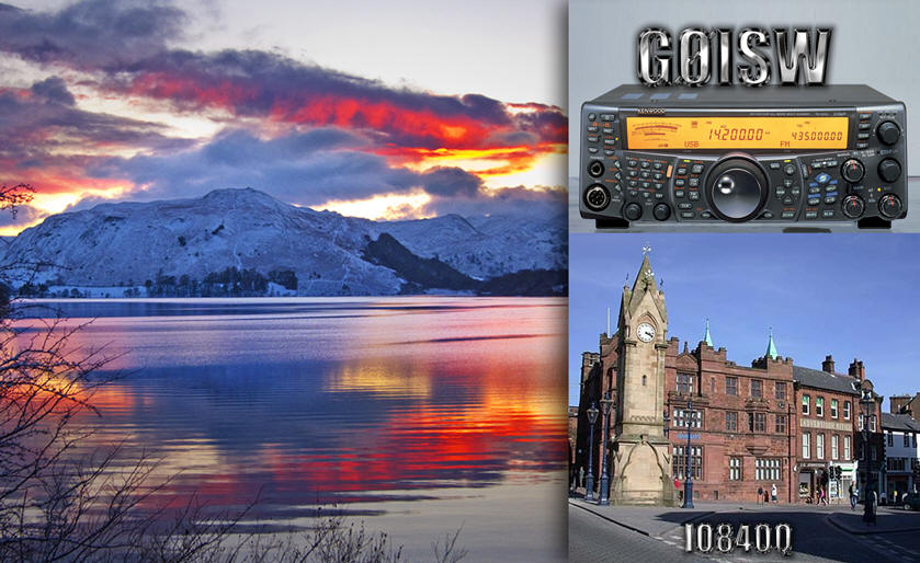
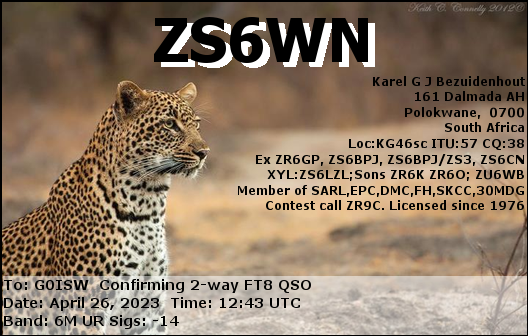
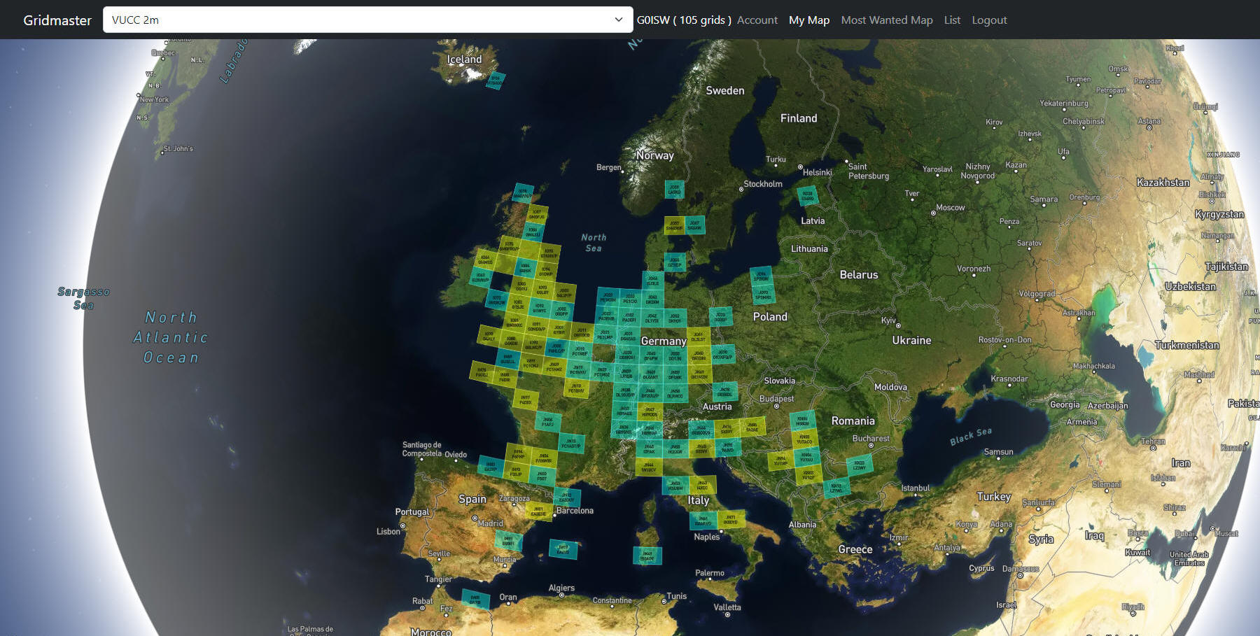


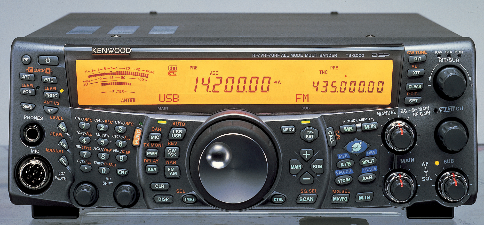
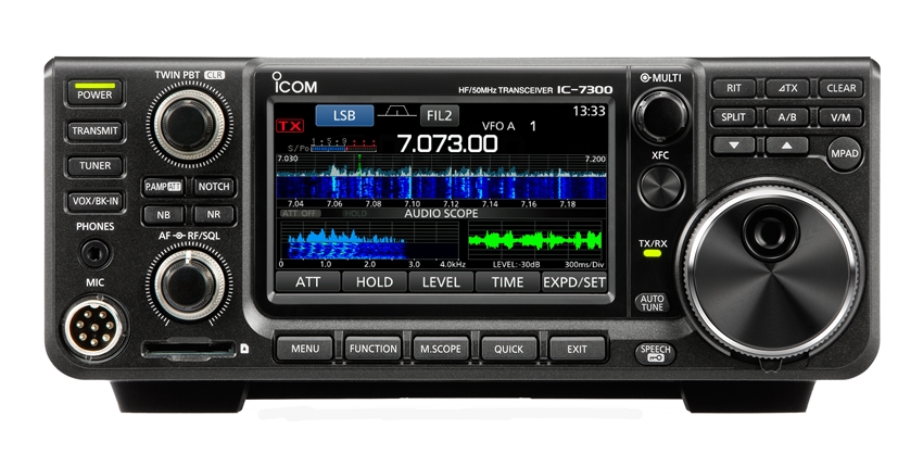
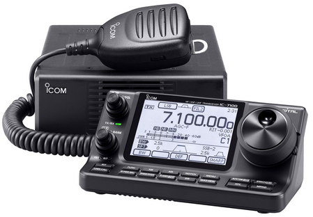
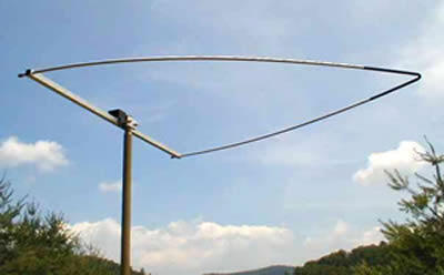
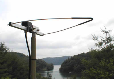
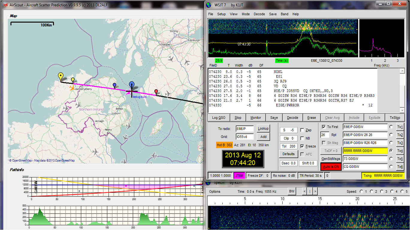
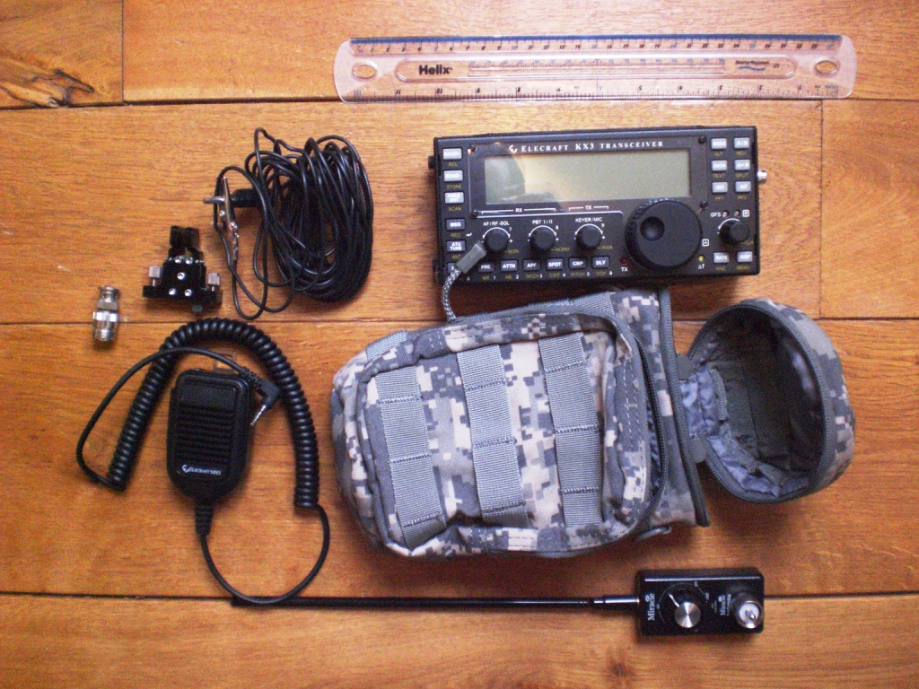
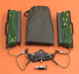


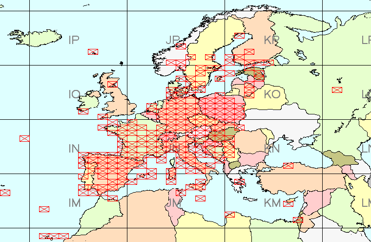
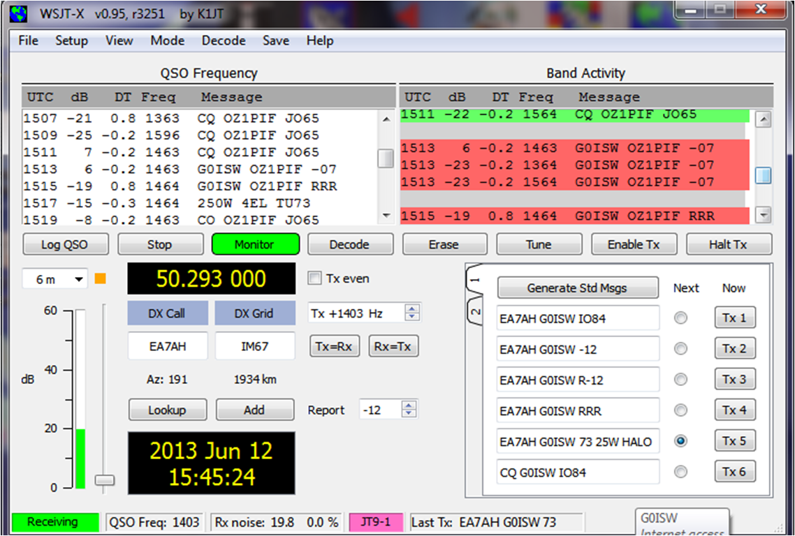
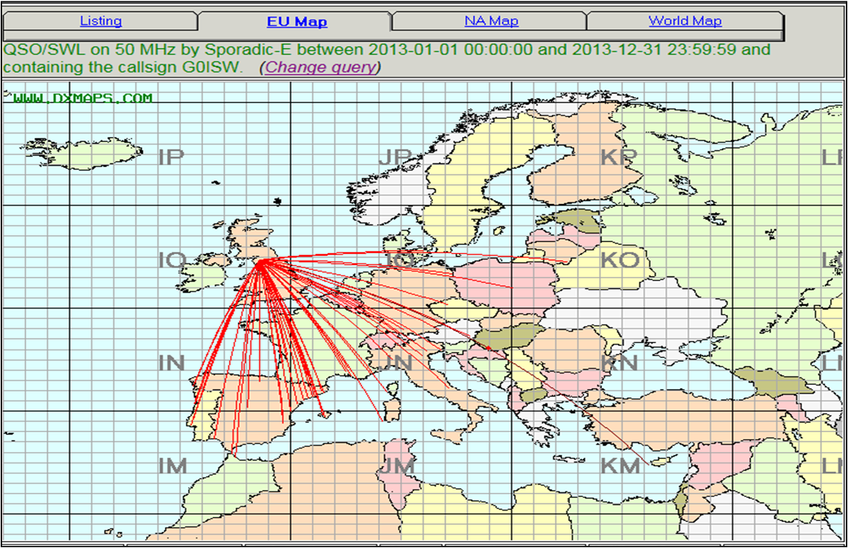
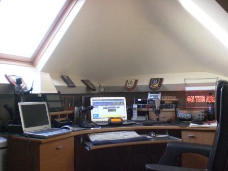
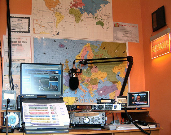
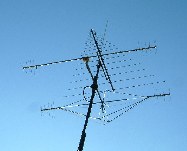


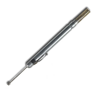

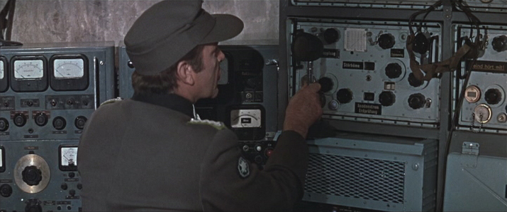


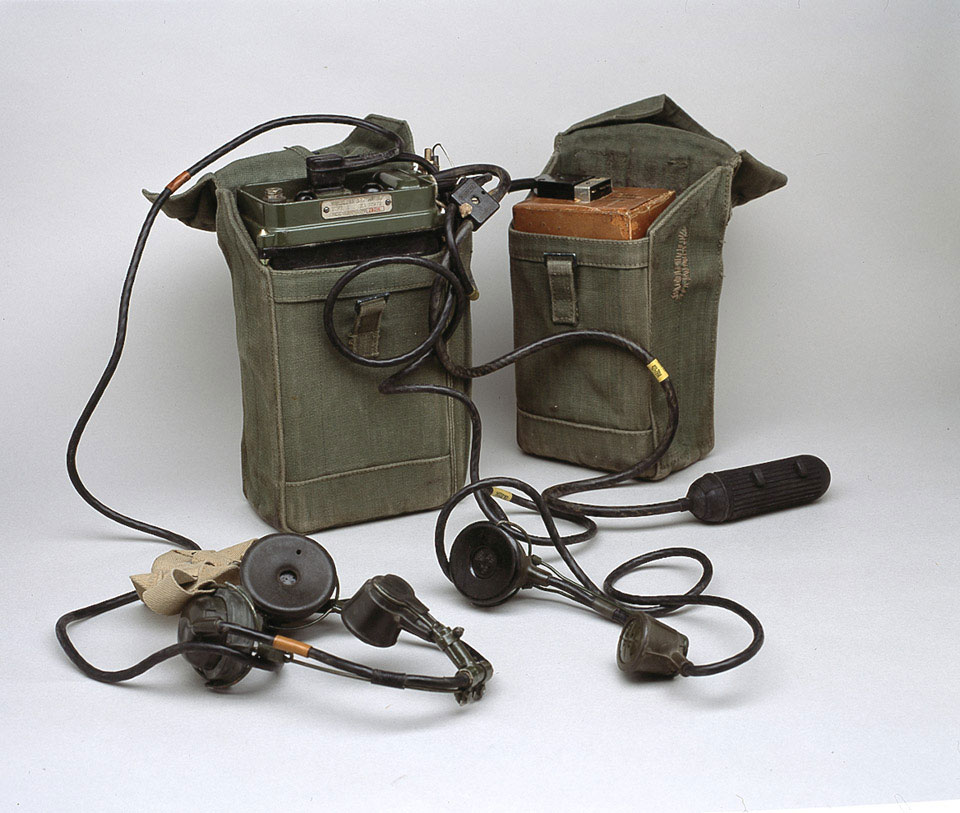

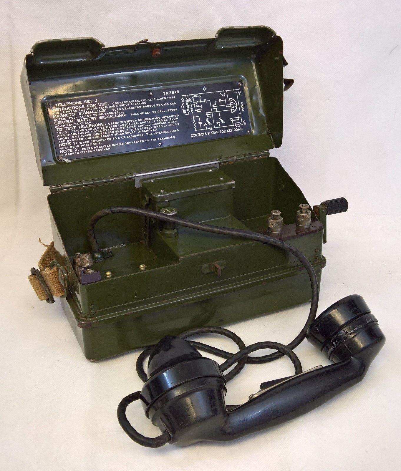
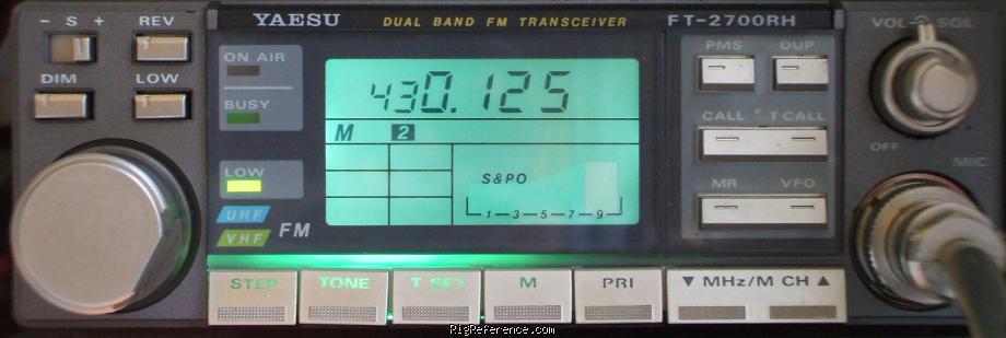

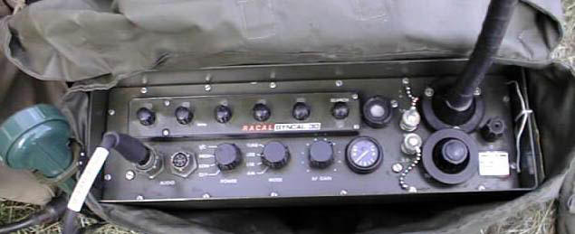


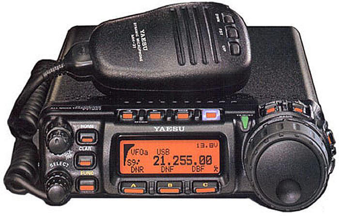


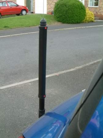
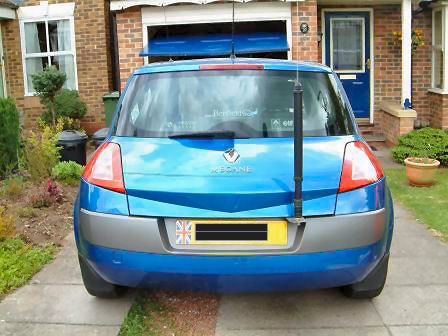
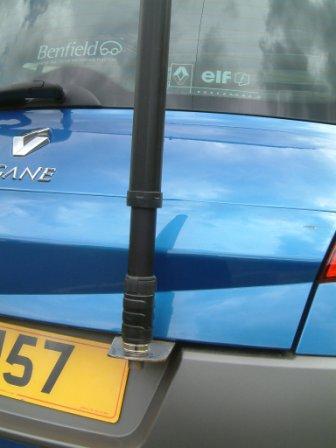


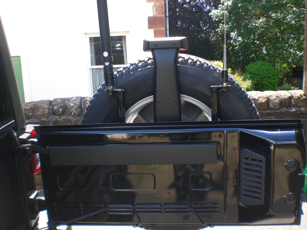
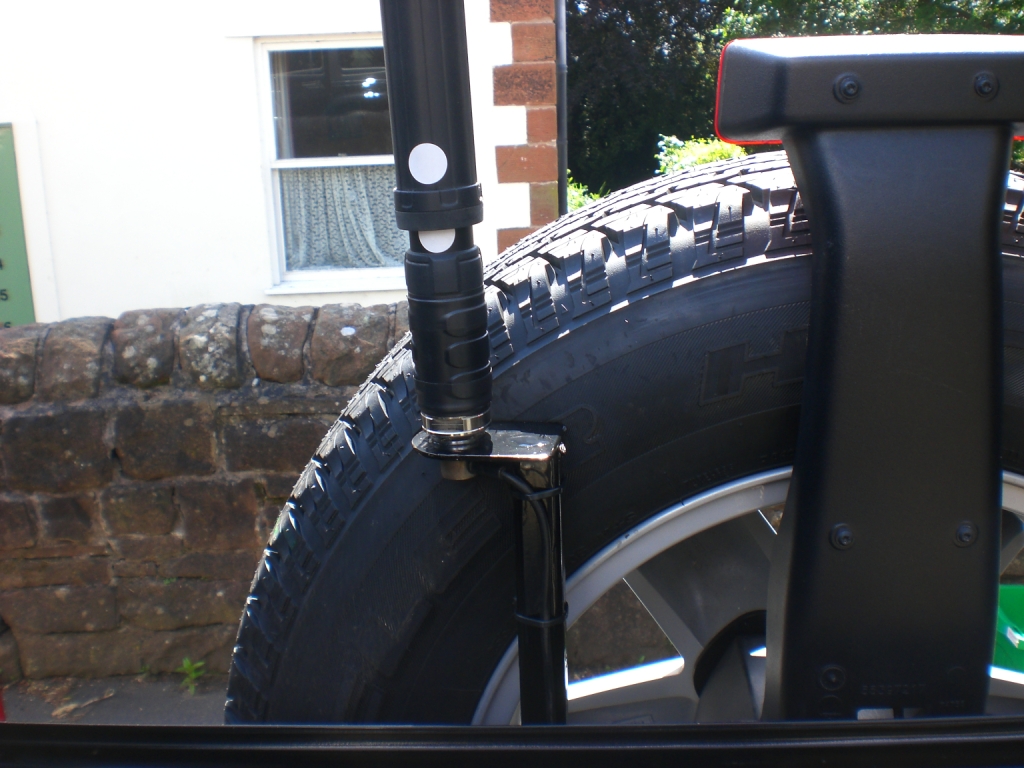
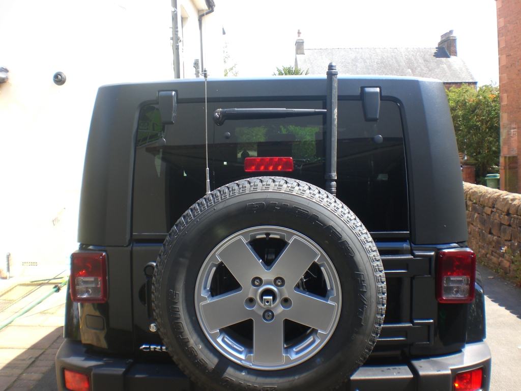

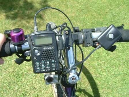
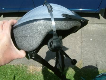
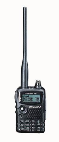
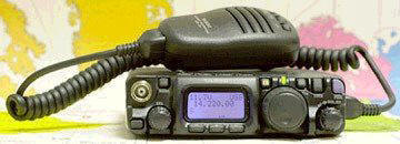
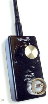
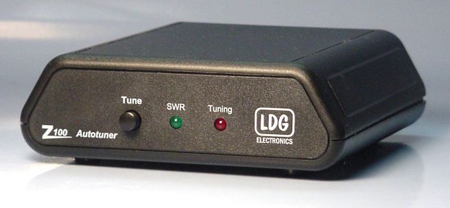
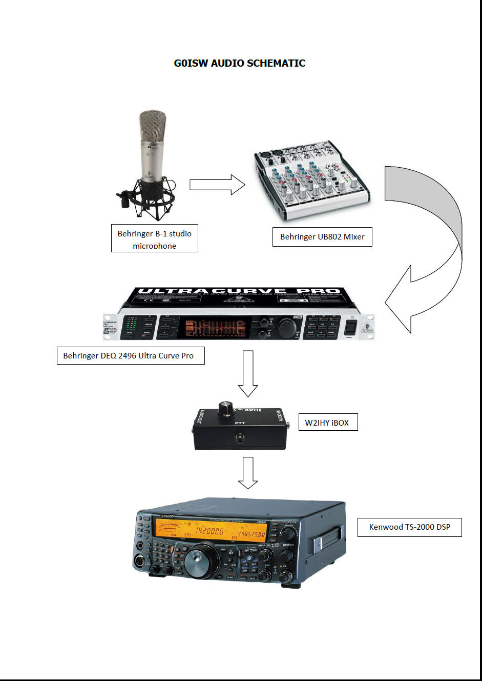

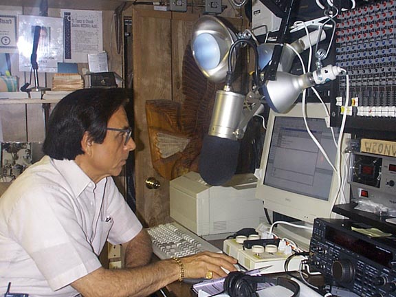
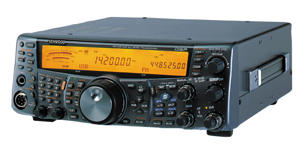
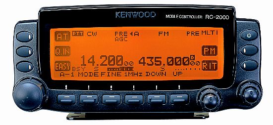

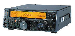
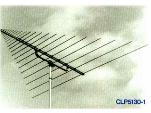
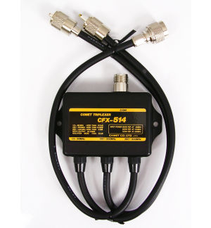

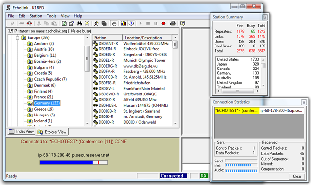
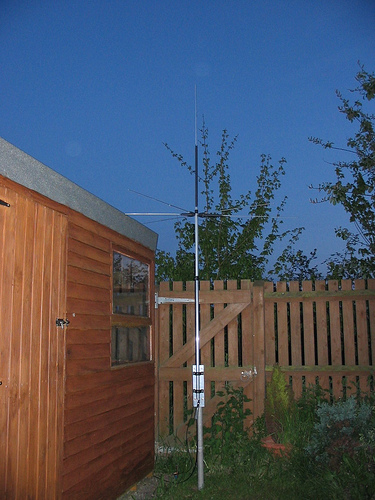
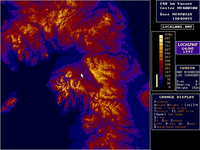
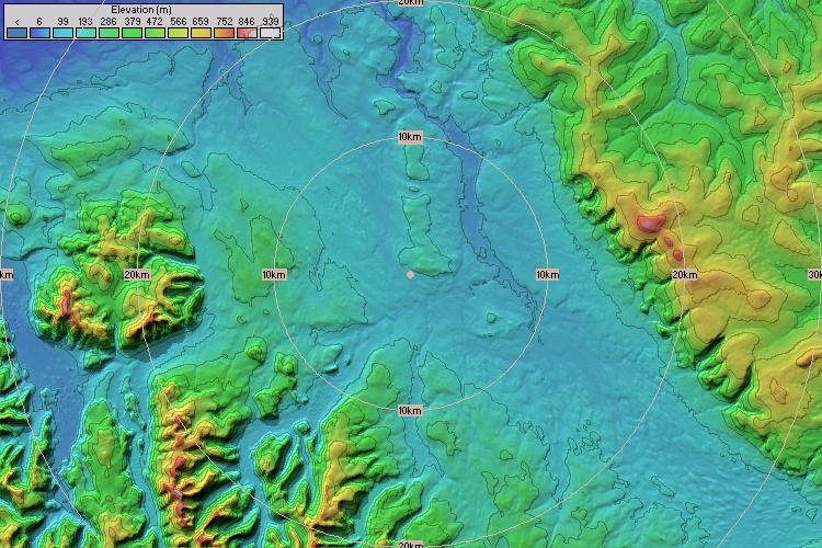
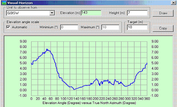
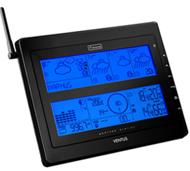
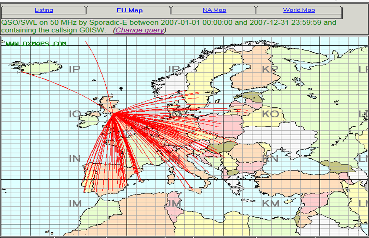
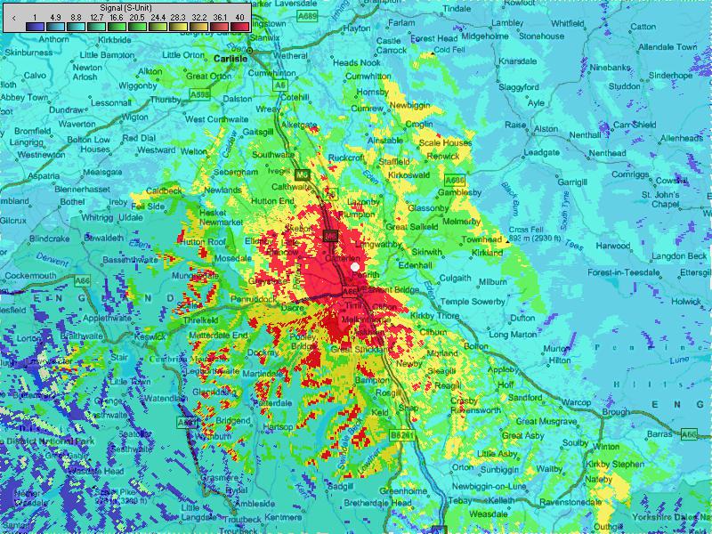
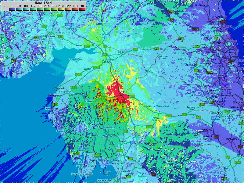


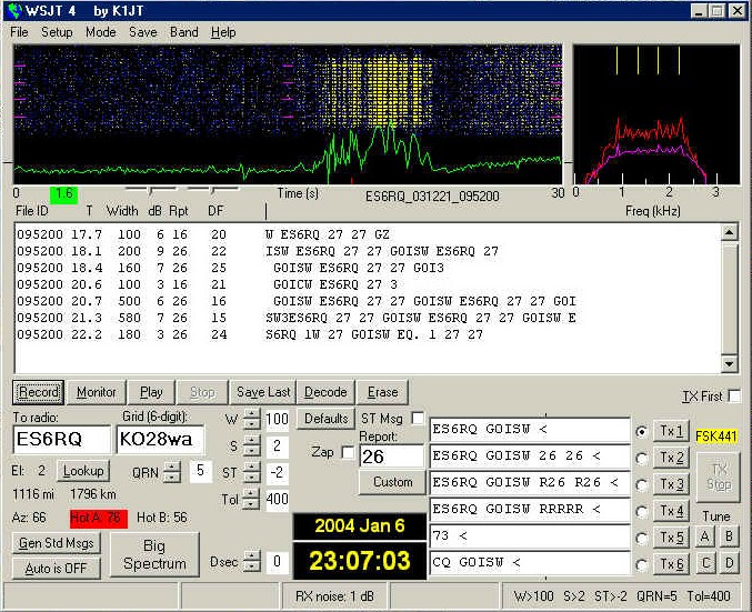
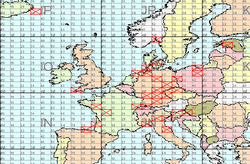
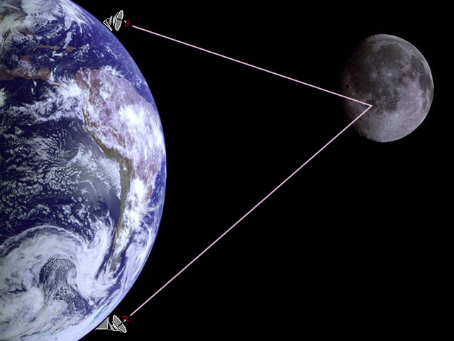
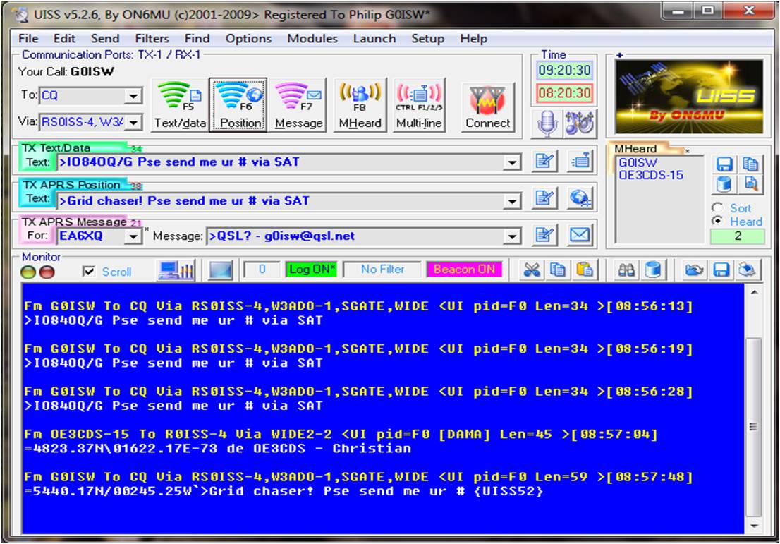
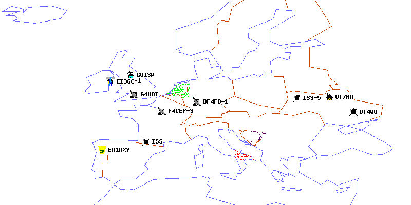
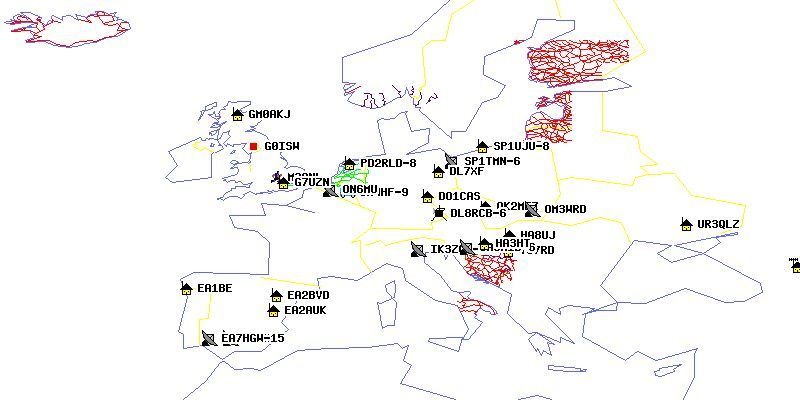
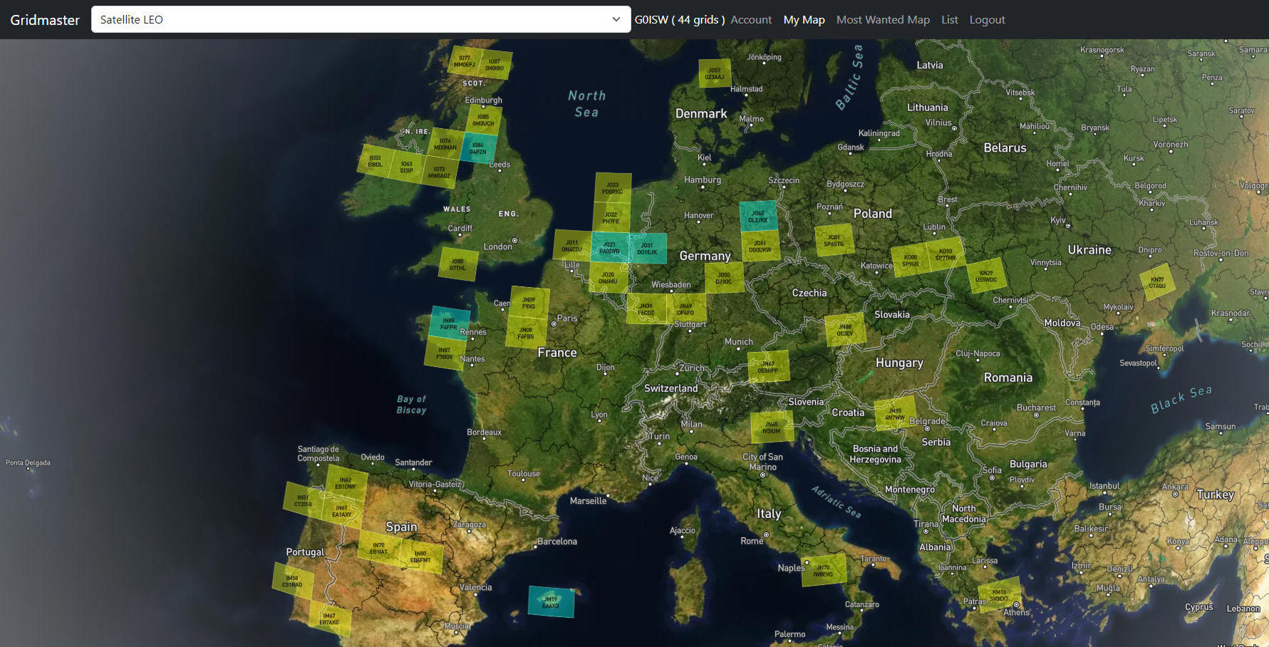
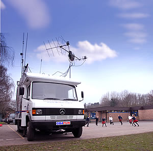
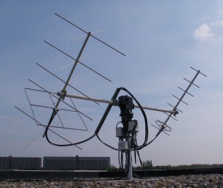


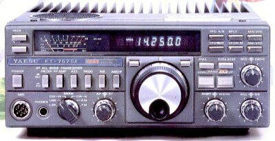
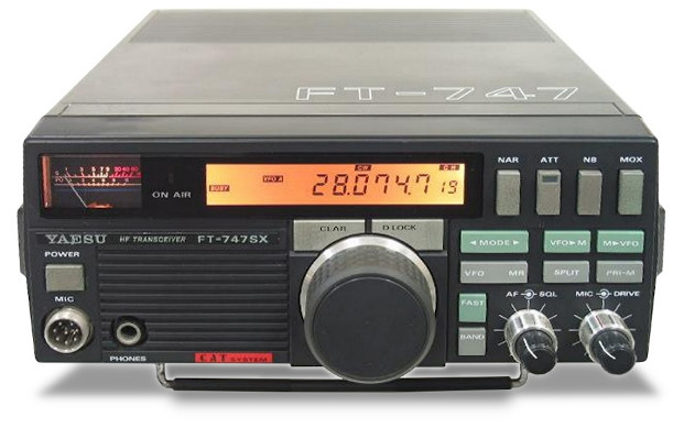
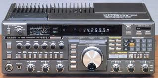

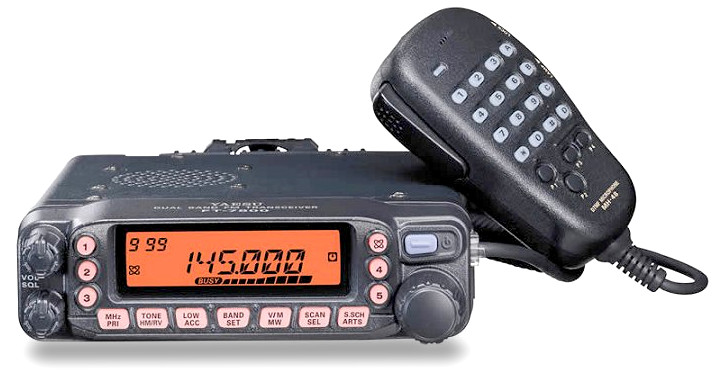

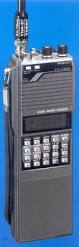
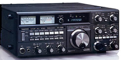

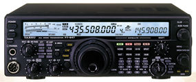


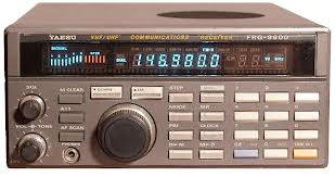
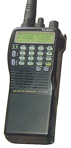

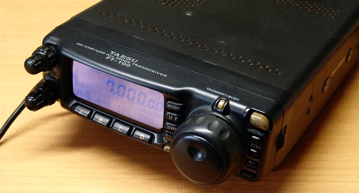
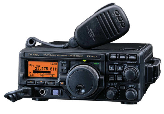

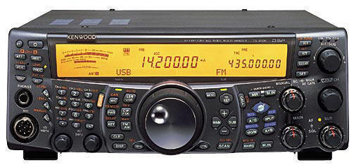
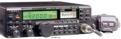
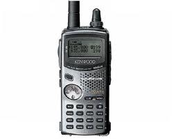
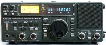
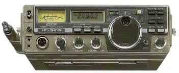


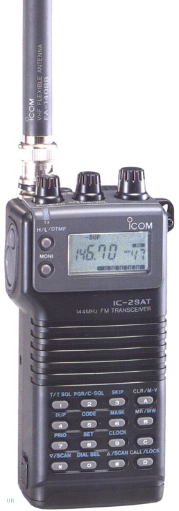


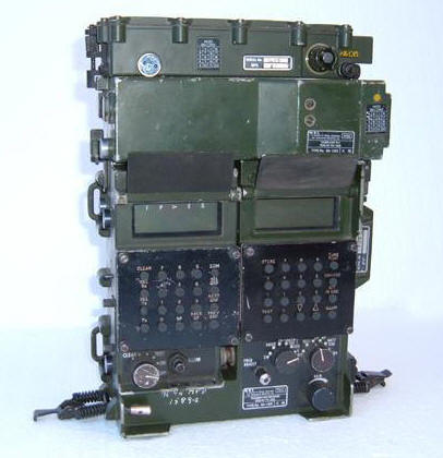
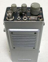
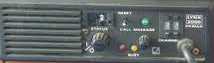

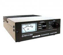
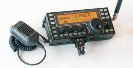
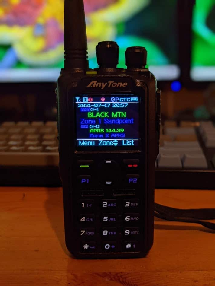
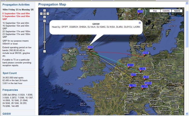
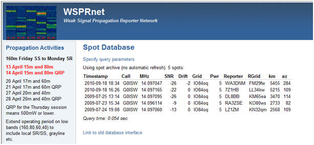
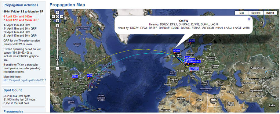
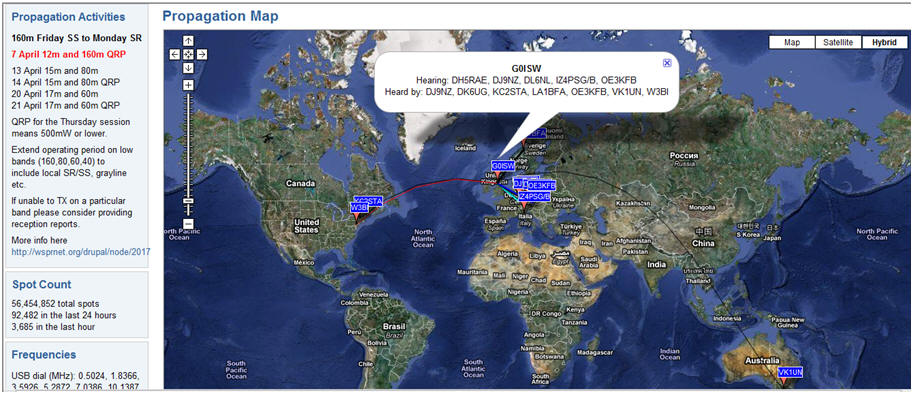
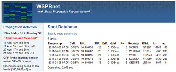
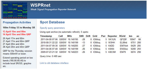


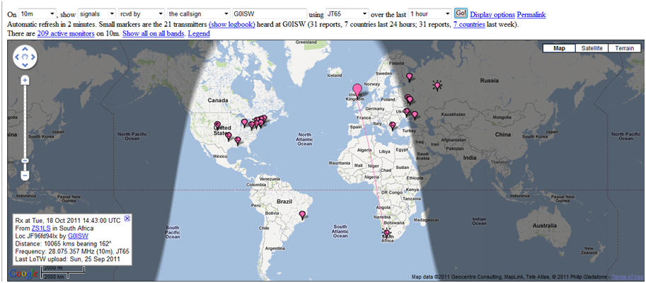
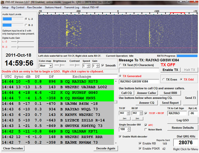

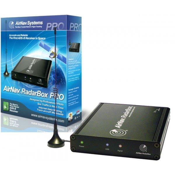
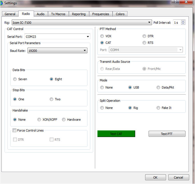
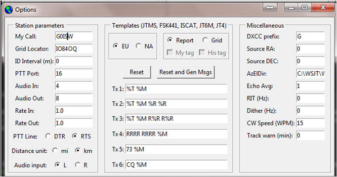
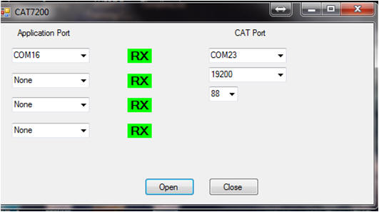


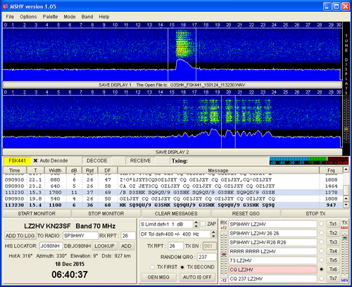

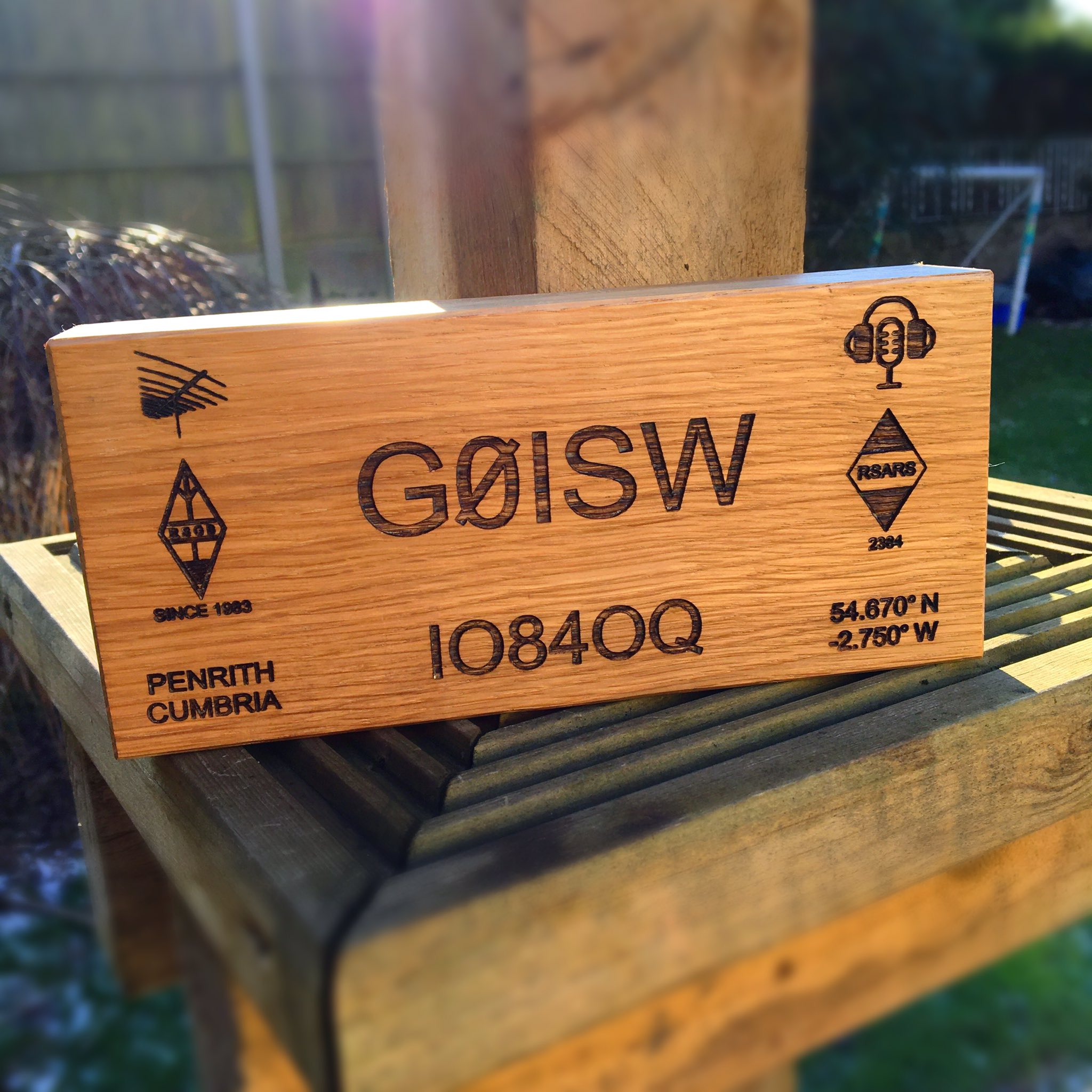
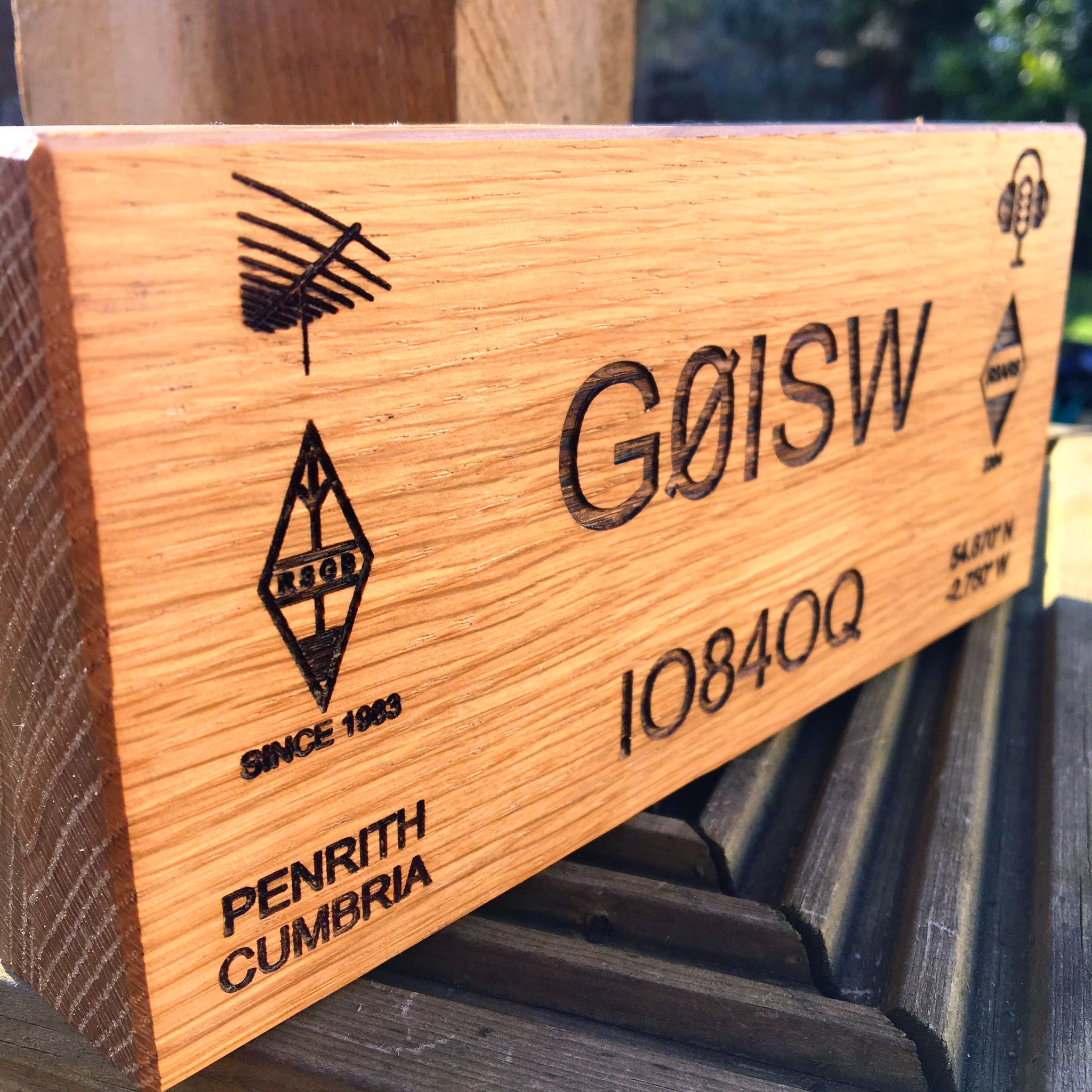
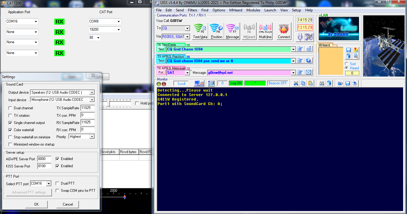
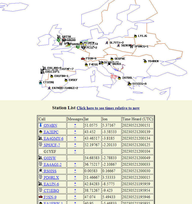
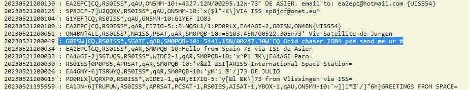


