 |
|
|
|
|
|
|
|
|
|
|
|
|
|
|
|
|
|
|
|
|
|
|
clamp the union onto the hardline, leaving some dielectric and the center con
|
|
|
|
|
|
|
|
|
|
|
leaving enough room to undo the connector. This means you DO NOT want to screw the connector body all the way onto the dielectric. Leave enough room to unscrew the connector sleeve. When you're happy, tighten the second nut on the compression fitting. This should cause the ferrule to clamp down on the rear of the PL-259. You could solder the ferrule-to barrel joint if you're paranoid, I guess.
There should be a small bit of center conductor poking out the PL-259 center pin. Solder it as you normally would, then trim it. Remember that the center conductor is only copper-plated, so it would be a good idea to allow the solder to wick back between the pin and center conductor for maximum joint strength.
If you want a female connector, you can use a 1/2" to 5/8 compression union with a SO-239 barrel connector. The difference is that the center conductor of the hardline requires a small piece of brass tubing to increase its diameter enough to engage the center contact of the barrel connector.
|
|
|
|
|
|
|
|
|
|
|
|
|
|
pression unions available at Home Depot.
What you want depends on what you need for a connector.
If you want to terminate in a PL-259, then a 1/2" to 1/2" compression union is what you need. You will also require a silver/teflon PL-259. Don't scrimp here. Radio Shack connectors are not acceptable!
Using the PL-259 body as a guide, measure one "body length" back from the cleanly cut end of the hardline, and, using a plumber's tubing cutter, cut through the aluminum outer jacket, and into the dielectric. I use a vise to grab the jacket and pull it off, but a pair of vice-grips or waterpump pliers should work well. Take the jacket and dielectric off, being careful not to nick the copper plated aluminum center conductor.
Now, using the body of the PL-259 again, measure another body length back from your first cut, and remove ONLY the aluminum jacket, leaving the dielectric intact. Disassemble the compression union. You should have two nuts, two ferrules and a center piece. The nut and ferrule may be a single assembly or they may be two separate parts.
|
|
|
|
|
|
|
|
|
|
|
|
 |
|
|
|
|
|
|
|
|
|
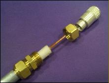
Step 3 - Push the nut and ferrule onto the coax shield Use NoAlOx and Scotchbrite to polish the shield 1 inch back from the end.
|
|
|
|
|
|
|
|
|
|
|
|
|
|
|
ductor extending out the other end.
Now, examine the center conductor carefully. There will be a clear plastic coating over the copper plating, which can be removed by starting a cut with a knife and then peeling the coating back. The center conductor is copper plated aluminum, so be careful not to nick it.
Take the other nut and ferrule, and loosely thread them onto the union. Take the PL-259, and slide it onto the center conductor, then screw it onto the
|
|
|
|
|
|
|
|
|
 |
|
|
|
|
 |
|
|
|
|
|
|
 |
|
|
|
|
|
|
|
|
|
|
|
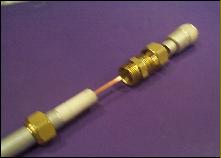
Step 5 - Add the second nut/ferrule don't tighten yet), then use a Tee connector to screw the PL-259 onto the dielectric, leaving just enough room to loosen the PL-259 clamp nut. You'll need to trim the hardline center conductor a bit, so do a trial fit first , before tightening the second nut/ferrule.
Solder the center conductor.
|
|
|
|
|
|
|
|
|
|
|
|
|
|
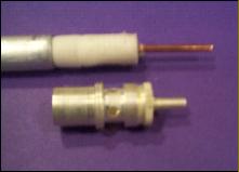
Step 2 - Use the body of the PL-259 as a length gauge when stripping the coax
|
|
|
|
|
|
|
|
|
|
|
|
|
|
|
|
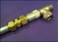
Step 4 - Push the union onto the hardline until the shield contacts the stop, then screw down the nut and ferrule you just installed.
|
|
|
|
|
|
|
|
|
|
|
|
|
|
|
Slide the nut and ferrule of the compression union onto the aluminum hardline. Use NoAlOx and a 3M scotchbrite pad to clean and coat the end of the aluminum for about an inch back from the cut you just made. Slide the center barrel of the union onto the hardline until it stops and tighten the nut and ferrule you have previously installed. This should firmly
|
|
|
|
|
|
|
|
|
|
|
|
|
|
|
|
|
|
|
|
|
|
dielectric, allowing the ferrule to slide over the rear of the connector body.
This is where it gets tricky. You want to get as much of the PL-259 body into the compression fitting as possible, while
|
|
|
|
|
|
|
|
|
|
 |
|
 |
|