|
Tower
and Carriage
|
|
You can click on photos to enlarge them.
|
 |
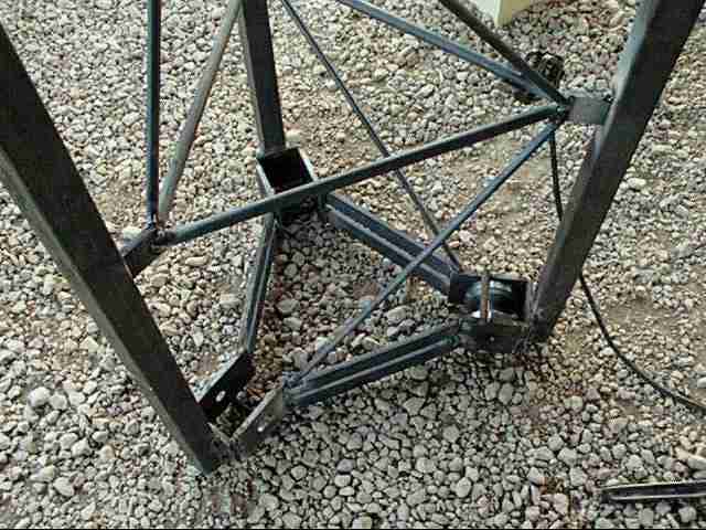
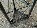
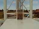
The
pullies of the sliding carriage:
6 pullies in a
triangular shape mouted on a greased staintess steel axle.
|
| |
|
 |
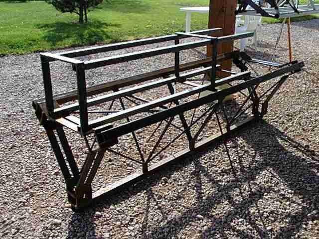
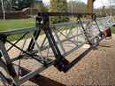
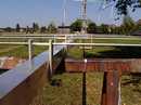
The
carriage:
2 meters high. It
surrounds the tower.
|
| |
|
 |
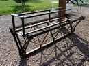
The
mounting of the pullies on the carriage:
The pullies have
to be positioned and soldered perfectly to permit easy movement of the
carriage on the tower without causing any mechancial resistance.
|
| |
|
|
|
Testing
the carriage:
Before
everything is solderd, one has to be sure that the carriage rolls up and
down through the whole length. After soldering also, some of the pieces may
move a little(because of the expansion of the heat and the cold)
|
| |
|
 |
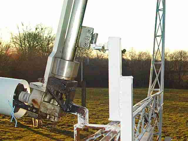
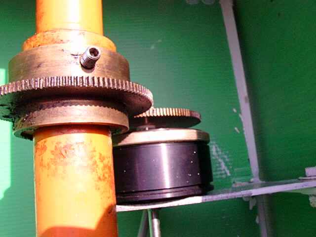
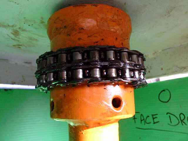
Mounting chassis rotor azimuth:
The azimuth motor
will be mounted inside.
|
| |
|
 |
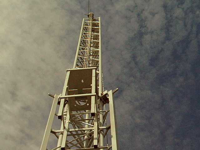
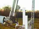
The
placement of the carriage:
The carriage is finally ready!
The
carriage is fitted on the tower. The placing of the carriage is fairly
easy because the tower is in the cranked down position. One can
distinguish on top: the rotor cage with the plates where the pulley system
will fastened.
|
| |
|
|
|
Pullies:
The tower is in
vertical position. The stainless steel cable is attached to the triple
sheave block which is composed of three movable pullies on the carriage
and three stationary pullies on the top of the tower.
|
| |
|
|

|
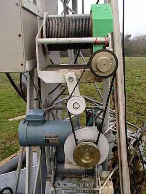
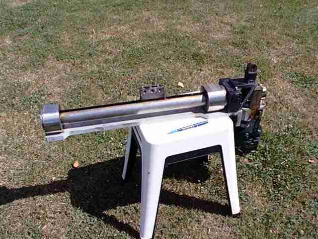
Winch
and motor:
A DC motor
with a variable speed control drives the winch.
Two pulley ratios
are installed.
|
| |
|
 |
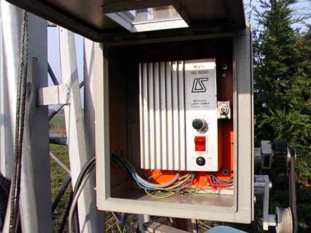
Speed
variator:
Box with the
speed electronic variator.
|
| |
|
 |
The
first raising of the carriage:
Reduced motor speed is important. The carriage goes up with no problem.
|
| |
|
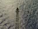 |
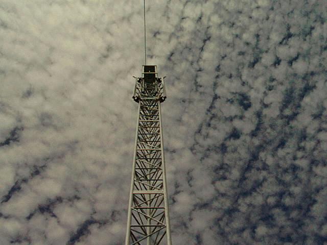
The
carriage at its highest postion:
For the first
time, the carriage is on the top of the tower, 13 meters up.
Emotion follows
and...satisfaction !!
|
| |
|
|
Elevation
and azimuth rotors
|
| |
|
 |
Elevation
rotor:
The full view of
the assembly
|
| |
|
 |
The
placement of the motor:
Placing the rotor on the horizontal beam.
After several
tries, the rotor is able to swivel round the beam at 90°.
|
| |
|
 |
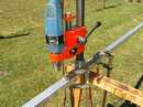
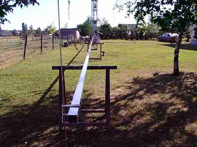
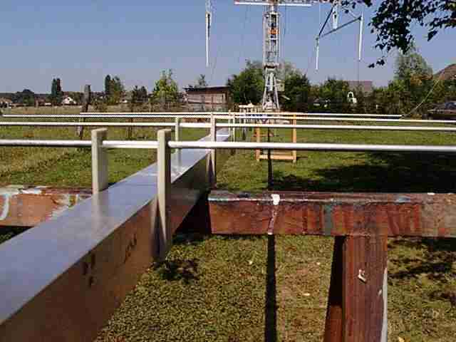
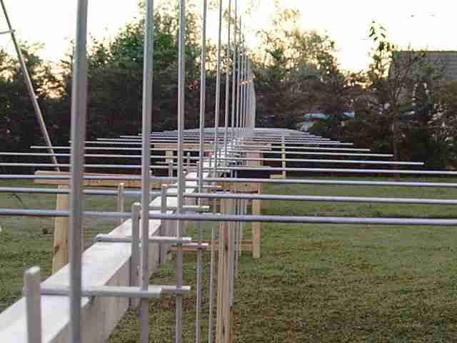
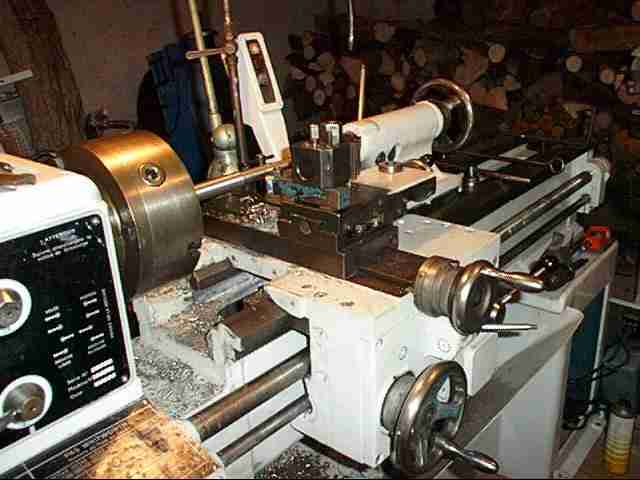
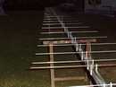
The
40mm boom:
The 16.50 meter
boom is placed on the sawhorse and drilled. Now I start to put on the U
brackets and the elements.
|
| |
|
 |
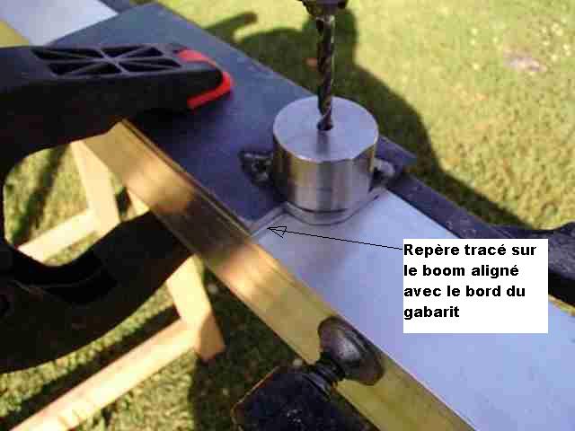
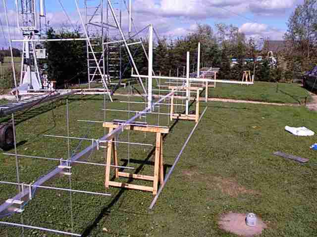
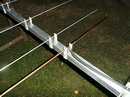
Placing
the elements:
Placing the first elements. The perceding step using the drill is very
important for good element alignment.
|
| |
|
 |
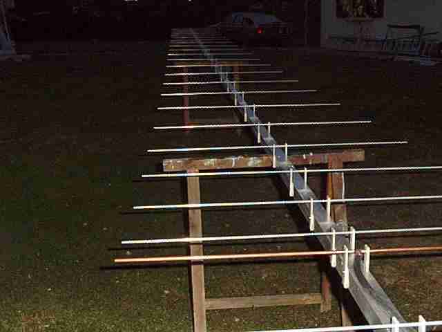
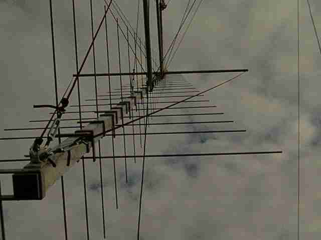
Placing
the elements:
It is getting
dark.
All the
horizontal elements are in place.
|
| |
|
 |
Dipole:
The coaxial cable is welded directly on the 2 elements copper of the dipole.
|
| |
|
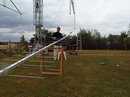 |
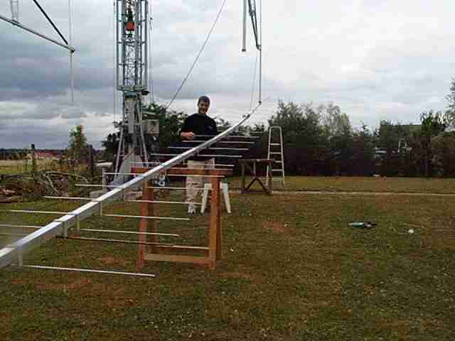
Installation
of the first antenna:
My son Nicolas gives me a serious helping hand to bring up this first
antenna. There are only at present the horizontal elements
|
| |
|
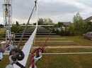 |
The rope
assembly of the antenna:
The horizontal
assembly with rope in dacron
(red and black).
The different tests in TX can begin. The results are good enough, but it remains me again to " to sharpen "
the impedance, the SWR of the antenna while displacing the 1st director very
easily.
|
| |
|
 |
First
antenna
OK:
The antenna functions
perfectly.
The temptation to
take the microphone is great. QSO,s begin with very good reports
|
| |
|
 |
2nd
polar:
The horizontal
antenna adjusted perfectly, I achieve the installation of the vertical
elements. These elements are baffled of 1/4 wave at the rear of the boom
for easier installation.
|
| |
|
 |
Vertical rigidity of the
boom:
2 tubes in
fiberglass are added on the upper part to permit the tension of the
rope in dacron. 2 stretchers are placed to the center of the boom + 1 to
the rear.
|
| |
|
 |
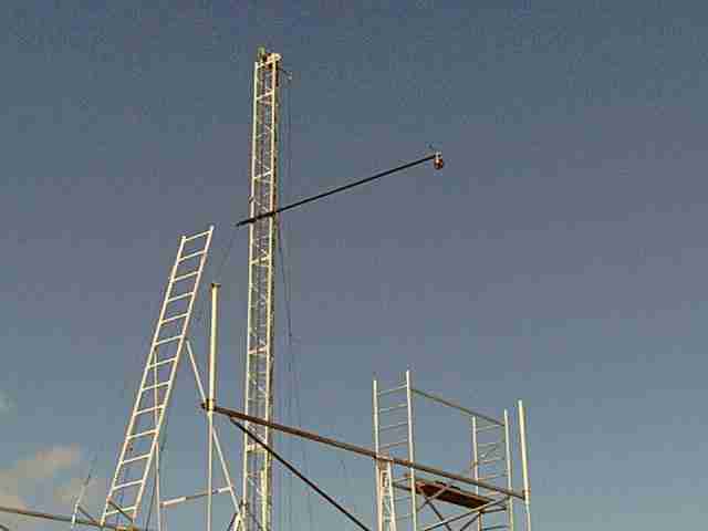
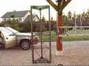
Arm
of lifting:
Arm of lifting with pulley in tip to raise the antenna.
|
| |
|
 |
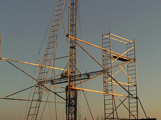
Setting
up high antenna:
It is necessary
to have 3 people at minimum to bring up the antenna. Some moments before the photo, my son was on the scaffolding, YL maintained the rope of
the lifting arm and me I was on ladder. That day, it was necessary so
possible, not wind!
|
| |
|
 |
Fixed
antenna:
Ouf...! the
antenna is finally put up after some working hours.
Not easy
!!
|
| |
|
 |
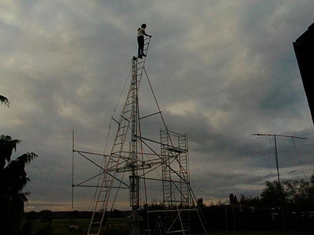
Seen
of the top of the ladder:
This is not the
place to be a clown!
|
| |
|
 |
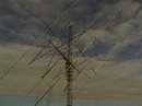
2
antennas:
The experience of
the first antenna, makes easier to put on the second one. That day, no
problems with Murphy's law!
|
| |
|
 |
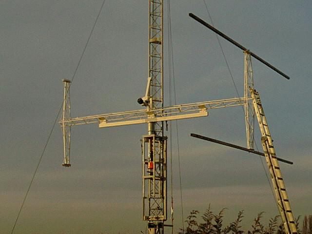
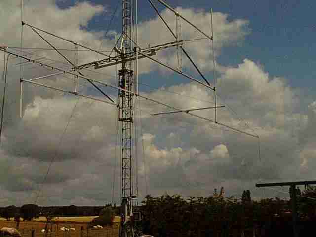
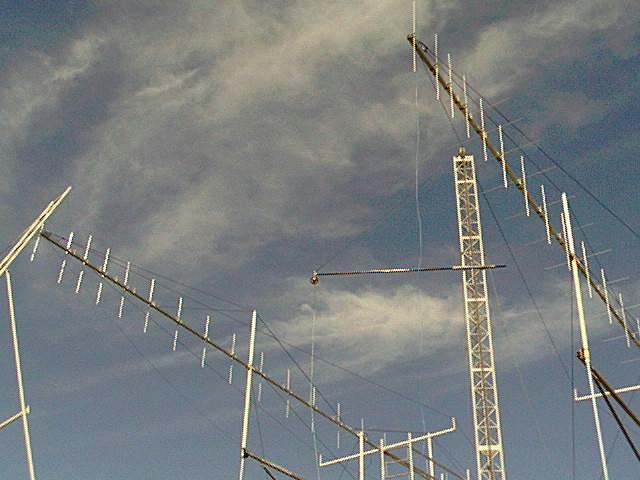
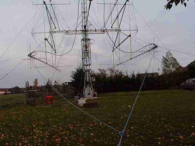
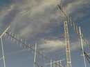
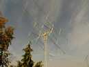
4
antennas:
A few days later,
the 4 yagis are put on, and I try out the site motion for the first time.
|
| |
|
 |
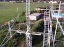
Rear
access:
While moving the
elevation of antennas and the height of the carriage, it is easy ta reach the
important parts of antennas.
|
| |
|
 |
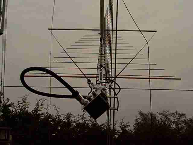
The
polarisation coaxial switch relay:
The coax switch
relay is fastened on the rear part of the boom.
|
|
|
 |
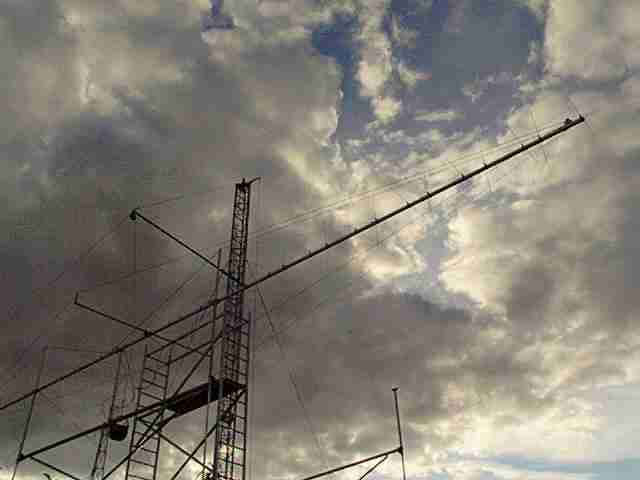
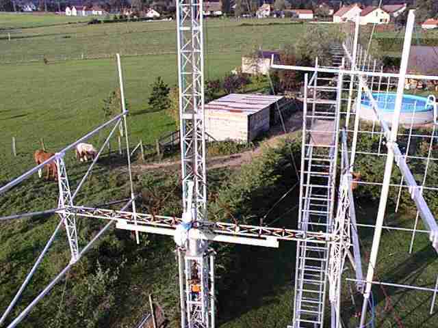
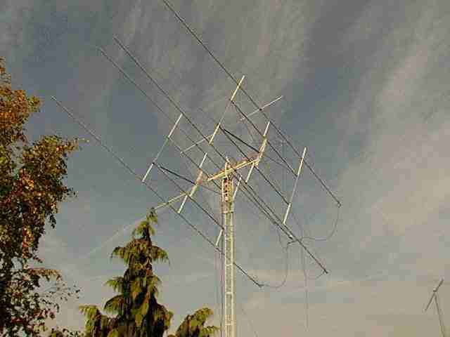
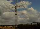
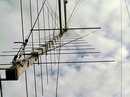
Antennas
at the top !!!
Couplings
are finished, everything runs well...! do the first mechanical tests with
the antennas: maximum height of the carriage, site and azimuth rotations,
all works well.
A few
stress! quickly
a photo !
|