Description of the antenna
-
Different topics of my fittings are described:The electrical features of the antenna, boom, support element on U brackets, dipole, coupling, antenna support, tower, sliding carriage, azimuth rotator support, site rotator.
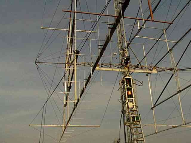
The boom is made of 40 mm square aluminium bar. The antenna lenght is 15,870 meters. The boom supports 25 elements diameter 5 mm for the horizontal polarization and also 25 other elements for the vertical polarization. All elements are fastened on U brackets made of polypropylene which are placed 30mm outside of the boom.
The vertical elements are shifted a 1/4 wave from the horizontal elements in order to get easier fitting for the U supports and dipoles (wiring, coaxial cable connections). This lengthens the boom of 520 mm and gives a total lenght of 16,390 m.
Supports
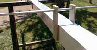
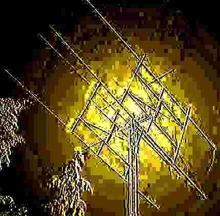
elements on U brackets
![]()
Why this type of assembly on U brackets ?
 |
|
|
For many reasons and advantages :
-
No modification of the elements lengh to do, compared with the width the boom. (different formulas with the correction coefficient !!)
-
Small drilling diameter (4mm) for fixing the U supports. A small loss of the mechanical boom resistance.
-
Opportunity to test the antenna by sliding the U support with elements on the boom before driling and riveting (ideal to test and improve my 1st antenna). During this test, it is possible to fix the U supports with adhesive tape.
-
Easy to remove for possible modifications.
-
Easy to center the elements.
-
Possibility to drill again very close to a hole which already exists.
-
The same for the dipole: very easy to position and to, line up on the boom with the other elements.
-
All the elements are insulated from the boom: no ageing of the antenna, no oxydization of the connection elements/boom.
UA quick advice: the polypropylene resists quite well to the UV ionization. After a long time, it is less breakable than the PVC.
The antenna had several simulations on my computer with several kinds of softwares.
I have simulated dozens of antennas, taking account of the gain, the F/B gain, the SWR, the current distribution, the boom gain/length effiency, the making possibilities, theze elements number, the radiance lobes of one or four antennas etc. Then, it was necessary to make a choice, to make the "good decision" and to embark on the project.
|
|
|
|
143.800
Mhz |
144.020
Mhz |
144.400
Mhz |
Gain |
16.60
dBd |
16.61
dBd |
16.61
dBd |
|
Rapport
AV/AR |
35.72 dB |
35.69 dB |
35.75 dB |
|
Impedance |
39.1
– j 2.8 |
40.0
– j 3.0 |
42.1
– j 4.2 |
|
T.O.S |
1.02 |
1.00 |
1.06 |
The gain
of the 4 antennas is 22.45 dBd.
The spacing of the antennas:
- on the horizontal is 5280 mm.
- on the vertical is 5220 mm.
The first secondary lobes are lobes –13dB of the principal lobe.
The
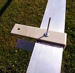
dipole
![]()
The dipoles are copper tubing of 8-10 gauge with a machined spacer of bakelite. The coax is directly soldered on the 2 copper pipes: the inner conductor on one side and the outer braid on the other (no balun, no center point etc.,) All (dipole, soldered points, coax) is isolated from humidity by a good coat of varnish.
The
Coupling

Each antenna is equipped with a coaxial relay mounted on the back end of the boom to tilt the polarization. This switching system allows considerable reduction of the back load of the antennas, by eliminating 4 coaxial braces and a 4 to 1 coupler.
I moved the center of gravity of each antenna by 1.20 meters toward the front of the braces to compensate for the excessive weight on the rear of the antennas.
The coax connectors between the horizontal dipole and the switch relay are cut at 1/2 wave lenght for the vertical dipole and 1/4 wave length for horizontal dipole. The electrical length of the coupling braces between the coaxial switches and the 4 to 1 coupler is 3 times 1/2 lengths.
The 4 to 1 coupler is fastened on the center at the rear of the H and is 6 meters away.
Next to the coupler is a watertight box containing the transmit/receive switch, the MGF 1302 preamplifier, and the 144/28 converter. The transmitting and the receiving operations are separate.
Mechanical
Description
The
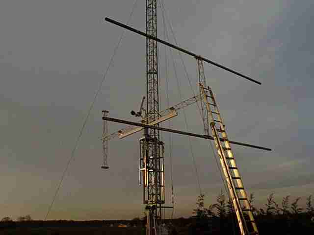
Antenna support
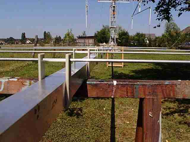
The antennas are mounted on fiber glass elements 50 mm in diameter and 1.5 metres in length. There are 3 "FLA mounting points" for a good mechanical connection with the boom. The other end of the element is maintained by universal mounting points on a 6 meter aluminum square with the width of 50 mm (held by 2 conical triangular tips) and reinforced in the form of a X, also made of aluminum pipe. The whole assembly is placed a home brew beam.
The boom is supported on the 2 sections by a 5mm Dacron rope (the length of the coefficent is 0). The aluminum structure is solidly reinforced by 7 mm stainless steel cables and by 6 mm nylon thread.
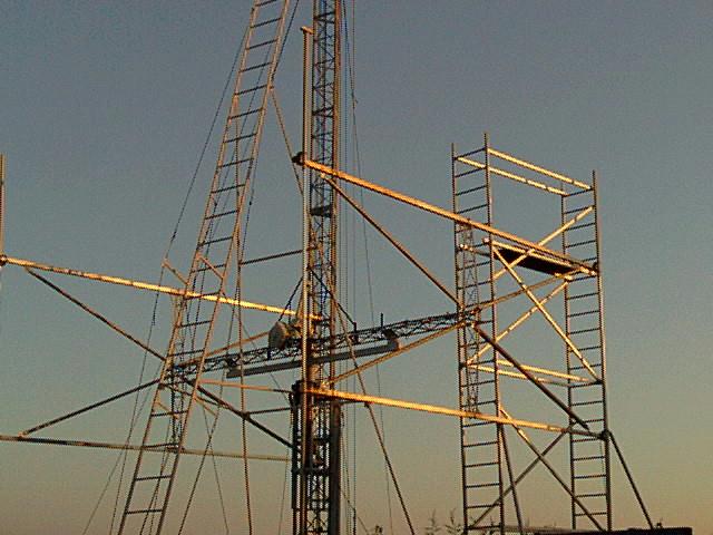
The triangular tower is home brew. The height is 12 meters and the width on one side is 0.42 meters. The tower is acrank-up tower with a heavy counter weight of 500kg at the base. I have been very careful to be the very correct in the assembly of the tower because the three sided carriage slides up and down easily.
I use two speeds: one speed is for going up at a slow speed with a flat notched belt, and fast speed for coming down with a trapezoidal belt. The speed for the motor is variable.
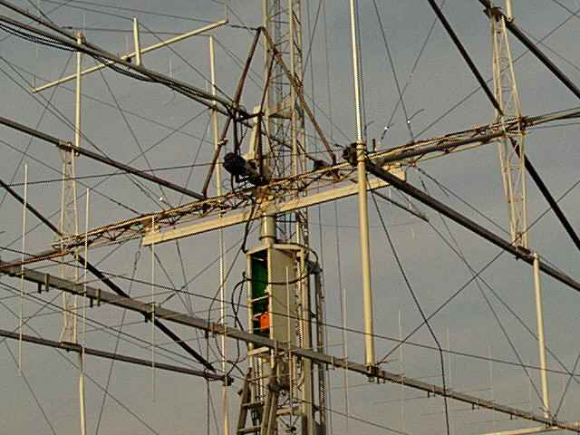
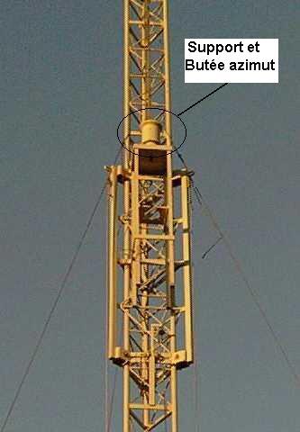
On the upper part, a kind of azimuth support with solid ball bearings and a ball bearing stop carries the whole mechanical and the aerials. This support is water tight, filled with grease and weighs 30 kg !!! It is attached to 1/200 reducer driven by a 24 volt DC motor. A locking system with grooves is ready in case of a huge wind gust. A flexible coupling is mounted on the end of the reducer. A double chain connection and two geared wheels couple the shaft of the rotor to the stop of the azimuth support.
The concept of the mechanical assembly is simple but the construction and the machining of the antenna are difficult as well as the movements of the antenna elevation (the opening angle and the two fixed points). Since the rotor being very close to the cable of the sliding carriage, we have to be careful not to let them bump into each other. A threaded rod drives a threaded cylinder. A fixed point on one side and the moving point on the beam allows the upper assembly to orient itself on the up and down elevation. A system with a reducer is driven by a DC motor rotates on the threaded rod.
Thank you to Jean-Claude F6FMB for his excellent hand with the site rotor.
An interessing remark: During the manufacture of this assembly, I thought two options:
1- to give a maximum elevation to the system,
2- to put the antennas at 90° elevation. In this way, I had easy access to the back ends of the four antennas with my two feet on the grass with no risk. Fine business. Moreover, just for the fun of it, I was able to adjust the height of the antennas while moving the carriage up and down. It was easy to check out all the delicate antenna connections (dipoles, soldering, coax, pre-amplifiers, etc.)