| Nikola Tesla | Theory | Basics | Measurements | My first TC | Magnifier project | Links | Homepage |

|
Practical Magnifier Construction PrinciplesMaking it work |
Last update |
An unavoidable preliminary in order to apprehend the subtleties of the Tesla Magnifier...
From the pages of Exotic Research Report magazine, January-March 1999 issue.
-
This was actually a pretty good article from Richard Hull in Virginia. It talks about
the magnifying extra coil setup Tesla developed in Coloroado Springs in 1899. Seems these
folks reproduced the configuration there and found out a lot of things about how the system
works-kind of a balancing act, as it were, something I've always felt when doing this work.
It's as much a matter of feel as anything. Anyway, here's the article, eventually...
"One watt-second of power is not much. As normally thought of, it is just one watt delivered over a period of one second. Oh what a vast difference however, can be the manifestation of one billion watts delivered for one billionth of a second."
-
There is a great gulf between the germ of an idea and its physical embodiment. Often
the originator of an idea carries his concept no farther than the philosophical stage where
musings and ruminations about possibilities are considered. Many times the idea is carried
through to the theory stage, often containing many mathematical entanglements. This
delights the acememic community, in their quest to give the idea a sound theoretical footing.
- The primary should be 3 to 5 turns and of relatively low inductance.
- The capacitor in the primary circuit should be relatively large.
- Small coils used a good single gap and over a kilowatt, a rotary gap was a must.
- A moderate terminal capacitance was needed to shield the top turn from corona leakage.
- Use heavy wire in the secondary and try to keep the turns count down and the inductance moderate.
- Use short, fat connectors throughout the primary circuit.
This was the prevailing school of thought.
By 1991 we had discovered that there are many easier and simpler ways to achieve incredible results from a two coil system. Many of these techniques flew in the face of the above conventions, but still obeyed scientific laws. The ultimate embodiment of our two coil system was the Nemesis system operated from 1991-1993.
One of our first observations was that large 12 turn primary inductances of many microhenries worked just great and allowed the use of much smaller capacitances. The primary heated a lot less (reduced eddy current losses). This gave a reduced di/dt which was a sacred cow to the radio theorist. With this, the primary connections could be quite sloppy. This does not imply that they should be!
We found that to counterbalance the increased primary inductance, massive secondary inductances could be brought into play. We further found that the moderate sized toroids then used could be increased by one full order of magnitude and the result would be a fantastic increase in the amount of energy handling capacity of a relatively small system! We determined that for moderate to large systems, a 2.5:1 ratio was a good length to diameter ratio for the output resonator.
We achieved superb performance up to 3800 watts with simple static series gaps of special construction. A rotary wasn't used until we went over 5000 watts. Why were we getting results equal to or better than the standard while flying in the face of convention? We determined that convention wasn't wrong, only that there were several ways to make Tesla coils as long as a synergistic balance was maintained between the components.
We would later find that Tesla, in his own Colorado Springs notes, would recommend relatively large primary inductances as long as the interrupt rate of the primary circuit was a small fraction of the resonant frequency. Our superior performing systems utilized what seemed to be grossly oversized terminal loadings for the resonator dimensions. This too would find an analog in Tesla's Wardenclyffe tower. We found that the secret was to load the resonator to the maximum point it could withsatnd without breaking down. We rapidly achieved arc lengths of four times the resonator winding length.
There were many secrets to be learned in ding this though. One was to never allow any wire to enter the resonator at the top or bottom under any circumstance! This is routinely done by the amateur community. We preferred the inverted cone archemedian spiral primary in a very shallow form. We provided an open, grounded guard ring around the outside primary turn in order to protect the primary circuit from the many impacts of arcs from the secondary. We developed special techniques of directing the output arcs without using the standard, energy wasting, take off rods. In short, we learned a lot about electrostatic field control.
The more we experimented and assembled systems, the more of the Corum's work we verified to our own satisfaction. The notes of Tesla also started to make more sense to us after many returns to them. It seemed that mathematics supplied only a basis to begin engineering efforts and would never be a rigid guidepost for the finished manufacture of systems. This we had also found to be the case within the two coil system. It became quickly apparent that the spark gap and resonator terminal loading were more critical to the magnifier system than the standard classic coil! More creative juices flowed as we worked out geometries for the driver system which would allow the very tight coupling demanded. We developed new rapid quenching gap systems for the task at hand. A number of photographs have been included showing some of our magnifier systems.
Like Tesla, we made some false assumptions based on limited empirical data, but ultimately with numerous different magnifier systems behind us, we literally began to get a feel for the system construction. This has an analog among production engineers of industry who have so thouroughly worked with just one system type that they develop an intrinsic feel for what works. Many of these subtleties do not jibe with theoretical machinizations, or answer the call of rigid mathematical formulae. They are often called... Fudge Factors, Catch-22s, Gotchas, etc, which often conspire to confound rigid engineering attempts.
I shall borrow from one of my fellow engineers in the group, Dave Sharpe, who so elegantly diagrammed the system conundrum of synergy balance, and supply a diagram here, (see figure 1). Imagine an ideal magnifier system as an inverted cone balanced on its apex with radial arms extending outward from its base which is now on top. On each of these arms is placed a sliding weight which represents vital system parameters such as spark gap dwell time and repetition rate, Primary inductance, primary capacitance, Secondary inductance, resonator inductance, resonator frequency, internal losses, applied voltage, top resonator terminal loading etc. As each parameter is adjusted, (ie. slides along its radial arm), the system is thrown out of balance and one, some, or all of the parameters are needed to be altered to bring the system back into harmonious balance. It is obvious that the system might be balanced in a thousand ways, but nonetheless, balance must be maintained. So there are many possible construction and operation avenues. The critical point that we learned in two coil construction was that the best system in the world can be operated in an improper manner. This is most often seen as improperly conditioned power from AC mains. Often the spark gap, which might be constructed perfectly, is not operated at its optimum point or lossy materials are used in coil forms or insulation.
What Are The Keys To Magnifier Success?
Power Conditioning
Input power must be conditioned in any magnifier using non-shunted transformers! The simple neon sign transformer can be used as is and requires no conditioning. This would place an upper limit on non-conditioned AC line power of under two kilowatts. We found these smaller magnifier systems were superb concept demonstrators, but the same power in the hands of an expert two coil builder could yield almost equivalent results. The magnifier really comes into its own at powers over two kilowatts! The best transformers are large potential transformers or small distribution transformers under 15KVA rating.We found the best control of the input energy was secured by mixing both resistive and inductive ballast in series with the power transorfmers primary winding. The resistance is often well under 1 ohm and the inductance under 5 milliHenries. These values are typical and will vary from system to system.
Without power conditioning, the main transformer will saturate and power will be wasted. If pure inductance is used, a see-saw action of the transformer and ballast can result in some frightening current exchanges between the two and uneven operation will result. Using only resistive ballasting, a large amount of energy is lost in heat. With a balance of the two, energy is saved, smooth operation is secured, and very long run times are possible at high powers.
Input Voltage
Only one rule applies here. The voltage must be as high as possible!!! Watch it though, many new and unfamiliar problems occur above 20, 000 volts. Corona and flashovers become a real system gremlin. The average coiler has little experience in this area and new techniques must be developed, not to mention the expense of extremely high voltage pulse capacitors. Tesla never ran his large systems with voltages over 20,000 volts more than enough times to destroy bottles within his capacitors and realize his materials were not up to the task. This is verified in the Colorado Springs Notes. Do not let anyone tell you differently. With reduced capacitance he could experiment above 30,000 volts, but shunned the practice. The desirablity of such high input voltages will become apparent with the discussion of the driver system.Spark Gap
A crucial component in a working magnifier is the spark gap system. Tesla's gap system in Colorado was very poor indeed and just barely sufficed for experimental purposes. He had trouble with it at the elevated input voltages during a few experiments.The Corums have led the way here, in that they tell us that the spark gap must quench in some tens of microseconds. This is beyond the casual coiler's gap inventory. Special gap construction is a must!
The secret is to not strain the gap. Break the arc up into as many individual arcs as possible to spread the energy out evenly over as many surfaces as possible. Also include a rotary in series within the chain somewhere. This is done to give a precisely controlled break rate and dwell period.
Any series gaps must be either vacuum or compressed air cooled within plenums. We have designed a special series arc rotary quench gap that can actually quench faster than required (also a bad condition). It is all in the operation and handling of the arc that the magnifier really sings. This is where the casual coiler is separated from the experimentalist. The gap is the bottleneck in any magnifier system.
Primary Tank Circuit
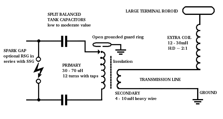
We tried many different primary tank circuit configurations and found Tesla's original Colorado Springs circuit to be the best operationally, but the most difficult to balance and adjust, (see figure 2). Tesla really knew his stuff.
The spark gap should appear across the power transformer's high voltage secondary and two absolutely matched and balanced capacitors should then be placed in the tank circuit connecting each side of the gap to the primary leads. Due to the critical need for tight coupling and conveying rapid rise time energy pulses to the primary coil, very short, fat low inductance connections must be used throughout. Tesla was forced to use a regulating coil to tune his primary tank circuit. This was terribly ruinous to his efficiency but was unavoidable with his physical configuration. You must not use such a device!!!!In smaller systems, we use a number of easily accessable turns, so tune and tap directly to the primary turns. Tesla's primary turns were one or two turns fully insulated and were neither accessable nor tappable. He paid a terrible price in reduced coupling coefficients as he allowed more off axis inductance to creep into his system. Fully, as much as 40% of his energy was lost in some experiments due to this one factor. Tesla commented that the system ran best with all turns out in the regulated coil. I don't doubt it one bit either.
The capacitors used for this work must be pulse types and have the lowest possible internal inductances so as not to rob system energies by creating off axis inductance or dissipating energy in the dielectric. We have termed Tesla's tank circuit the Tesla equidrive circuit. One must be capacitor rich in order to tune the circuit over a broad range with capacitance. Tesla was able to do this over a limited range in 1899 by adjusting the number of bottles in one tank on each side of his capacitor bank. The modern amateur is best advised to tap the primary coil directly. Naturally, all of the classic primary tank circuits will work but the equidrive circuit seems to yield the most power.
There is grave danger in this circuit! The series capacitors pose a life threatening hazard after power shutdown. There is a good chance, depending upon the point during the AC cycle when power was removed, that the capacitors will retain a dangerous charge. If this circuit is used, do not tune or touch the primary circuit until both capacitors have been discharged!
The Driver System
The driver is composed of the primary and secondary coils. This is not a resonant system! This is not a Tesla coil. This is a low impedance, tightly coupled, oscillation transformer, fully obeying simple transformer action whose output frequency is determined by the primary tune and secondary frequency splitting. Nothing is resonating here as quarter or half wave line!
Since the output voltage of the secondary is determined by the simple turns ratio and coupling factor, we want the highest input voltage to the primary as possible. The critical requirement of this driver is that it has the lowest possible impedance with reference to ground. Having said this, it can be seen that two critical requirements must be met.
The first is the very finest ground connection must be secured! The casual coiler cannot begin to appreciate this statement. Tesla once said that the bulk of the expense for the Wardenclyffe tower was in the incredibly deep and labor intensive grounding system he required in order to secure a firm grip upon the earth.
The second important part of the foregoing involves using wire with a large surface area for the secondary winding. This reduces the internal RF losses of the secondary and further lowers the output impedance.
Generalizations are overabundant in the Tesla coil community but I am forced by space to say that the inductance of the secondary should be low to moderate. We have found that 4-10 millihenries works well for the medium sized systems.
Needless to say from the above discussion, the resonant frequency is not critical, as nothing resonates. If one must characterize things, the quarter wave resonant frequency of the driver secondary should be at least two to four times higher than the resonant frequency of the third or extra coil which is the true output device of the system. The primary is built along more conventional lines. Heavy walled copper tubing is the best material here. We prefer moderate to high inductances between 30 and 70 microhenries. This allows the use of more economical capacitances.
One thing we have always found amazing is the tendancy of many builders to place large amounts of capacitance in the primary circuit! In some cases we have seen as much as 0.2 microfarads of capacitance was used on a 6 kilowatt Tesla coil which produced 6 to 7 feet of arc. It is amusing to remember that Tesla was able to get fantastic results from a huge 50 foot diameter system that used no more than 0.153 microfarads of capacitance. It just shows how far out of balance some systems can be.
When we hear of a builder that uses more than 0.1 uF of capacitance, we wonder about the builder. Our 10Kw Nemesis used only 0.09 uF of capacitance and produced straight line, point to point arcs of 14-15 feet. We believe this system could have produced longer arcs, but we were space limited. Large capacitances are best used only with low voltage input systems where increased energy is needed. The magnifier normally uses very high input voltages and can utilize a smaller capacitance.
The coupling between the driver primary and the secondary is crucial to the operation of the system. It is the main distinguishing feature between a magnifier and a normal, classic two coil system. This is where all of the power handling capability of the magnifier is derived. Most Tesla normally operate between K=0.05-0.15. The magnifier requires couplings over 4 times greater (K=0.4-0.6). For simplification, the closer the primary is placed to the secondary, the greater the coupling. Some of our work of late has been in investigating the use of various possible flux concentrations to assist in this area.
Finally, there is the question of insulation between the primary and secondary. With coupling factors of K=0.4-0.6, the proximity of the primary to secondary will break down air easily. We use large 90 mil thick sheets of polyethylene in multiple layers to suppress the arcs and corona. We are currently investigating oil immersion of the driver system to eliminate many or the driver insulation problems. One arc from primary to secondary will destroy the driver instantly. The current intensity of one of these arcs must be seen to be believed.
Tesla damaged the dynamos of the Colorado power plant, but not while running his magnifier and overloading the generators as so many of you have been led to believe. He overloaded nothing! He had disconnected the extra coil and was arcing the secondary driver output to ground when the short waves created by this terrifying process traveled back to the dynamos and faulted their insulation! Once the dynamos insulation broke down, they power-arced and destroyed themselves. Where did we hear this new stuff? From Tesla's own pen! It is clearly and fully delineated in the Colorado Springs Notes.
The Resonator (Extra Coil)
The power from the low impedance driver is coupled directly to the base of the resonator or extra coil, which is a quarter wave helix, via a transmission line which can be any large copper surface such as round pipe. Surface area is a must have item here. A lot of RF energy is being transported clear of the nasty and disruptive magnetic field of the driver. Don't fail to supply a good conductor here. The resonator, or extra coil as Tesla termed it, is the real source of voltage and power in this system. Again, use large wire and good low loss materials here.We have run extensive tests on materials and wood, paper, cardboard, phenolic tubing and other such materials must be avoided at all costs. The best materials are modern thermoplastics. The best of these being Teflon, polypropylene, polyethylene, styrene and PVC. Don't use granpa's pretty stuff. Use what the intervening 100 years has given you to better the system. Tesla would have !
Tesla gives us an important hint as to the inductance of the extra coil. He says that the extra coils momentum, (inductance), must preponderate over that of the secondary. This makes sense too. We are striking a bell, (the resonator) with a clapper, (the driver). A 12 ounce silver bell would be ill served by a one ton clapper. The inductance of the resonator should be at least three times that of the secondary. We don't want the driver overpowering and swamping the resonator.
In engineering terms we want to match the impedance of the driver to the base of the resonator. For the calculating crowd, we refer you to the Corum's excellent PC program, TC Tutor. My task here is to put you on the right path without tangling you up in your underwear. A bit of experiment will verify what Tesla, the Corums and I say. The pictures included here will serve as proof enough for most.
The resonator must be viewed as an isolated system! This includes its terminal capacitance which has the effect of storing energy, electrostaticaly shielding the top of the coil and lowering the base impedance of the resonator. This allows for increased base current which translates directly into more output voltage and energy. Odd, that is just what we are looking for! The purity of a free ringing, unfettered resonator cannot be appreciated by the casual coiler until viewed first hand.
We prefer to use a wire gauge equal to or just smaller than that contained in the driver's secondary coil. The resonator's final resonant frequency is more determined by the terminal capacitance than by the wire winding in our machines. We have settled on a ratio of less than 2:1 for the extra coil's L:D ratio. Our best systems are often 1.5:1. We have achieved sparks of 7 times the resonator winding length which Tesla never seemed to achieve, according to his notes. We attribute this to modern materials and more efficient gap systems than he had available.
Plus, we have the benefit of modern theoretical work of the Corums and well developed transmission line theory. In all of our work, we have noted that the largest toroid possible always tends to extend the results of the system. The terminal capacitance should dwarf the resonator if spark is desired.
Current Work By Our Group
We are regularly breaking our own records as the experimental work with magnifiers progresses. We have a good deal of new ideas planned for future investigation. It seems that when real work is analyzed, there are 10 new ideas that result from the experiment.The principal magnifier developers in our group get together often for brainstorming sessions. Such sessions are very fruitful and separate from our monthly meetings. We have decided on a number of modular approaches to magnifier construction. The key to our success is the construction of numerous magnifier systems of vastly different characteristics. Rather than build just one system and refine it forever, we tend to build a system, refine it as much as possible and determine its limitations. We then tear it down and construct another system using knowledge based on the experiences acquired from the previous system. We number each system and currently are working on magnifier #9.
The power levels utilized range from 300 watts to 10,000 watts. We have never achieved less than 3 times the resonator winding length in spark and have recently exceeded 7 times that length as the system efficiencies increase. We share our information openly with others via our video report tapes and educational series tapes14. We have published information in The Tesla Coil Builders Association News, Electric Spacecraft Journal and R & D Innovator. We have met some of the most wonderful people at our yearly Teslathons in Virginia.
It is important that good information see the widest possible dissemination. There are just too many false starts based on untried information or pie-in-the-sky theoretical approaches. We have sought to document our work at every step of the process via video, still photography and the written word. We have over 450 still photographic images and offer over 100 hours of video tape reports as proof of our work based on real experimental efforts.
Summary
The limits of the system hold to Telsa's original verbiage, that the system limits are so remote that they are imposed only by the limits of the components and materials to tolerate the strain. This is where our efficiencies far exceed Tesla's. Modern materials and techniques allow almost a full order of magnitude reduction of the Colorado Springs machine. The input power handling capacity per unit volume has increased dramatically and there is a wide open field for the Tesla coil builder or experimentor.We tend to use mathematics as a tool rather than a crutch. It was once said when equating mathematics to a lamp post, that a good scientist will use it for illumination. A bad scientist, like a drunkard, will tend to use it for support. We have made many mistakes and our failures outnumber our successes. We have worked from false assumptions and probably will continue to stumble now and then. We are, however, confident that ultimately we will understand as Tesla did, the intricacies of the magnifier system.
We are still aggressively pursuing magnifier research and, like Tesla, have completely abandoned the two coil system. We have added many new insights for construction and shared them with the Tesla coil building community. I hope we have also opened new areas for amateurs and professionals to assist in the discovery of new and innovative techniques.
__RH
In our modern age it is sad to say that in many instances mathematics is often the language of all ideas and many academicians are quite happy to fold their hands at this point and consider the matter closed or at least leave the hands on stuff to the engineers, technicians and manufacturers. The true experimentalist takes and idea through an experimental phase and finally to a working model. Much of research today revolves around big science, with multi-million dollar instrumentation and multi-million dollar installations. How can a lone wolf inventor play the game?
Nikola Tesla was one of those people that come along rarely in science whose ideas always came along faster than they could be developed. His funding was limited and his ties to established institutions and industry were virtually nonexistent. His inventions of alternating current electrical motors and distributiuon of polyphase currents secured for him a reputation of the greatest living electrician by the mid 1890's. In his own time, people knew that Tesla was a brilliant experimentalist and discoverer. His interests turned to high frequency oscillations and he invented a resonance based transformer system which is known as the Tesla coil.
It is not the purpose of this paper to give the detailed whys and wherefores of Tesla coil theory. The Corums have covered this in some detail at previous symposia and in a number of articles. The reader is referred to their work for fine details. I will however give a broad and rapid overview of the basics of the Tesla coil and ultimately the magnifier.
The classic two coil Tesla oscillator consists of a primary tuned circuit and a loosely magneticly coupled resonator, (usually 1/4 wave resonant) which uses internal resonance within the resonator to create huge output voltages. These voltages are, in general, limited by the inductance ratios of the two coils and their internal losses. Telsa realized quickly that the power capabilities of this seminal device were limited by the required loose coupling of the resonator.
If the coupling of the standard two coil Tesla oscillator is increased to yield more efficient power conversion, then the resonator and the primary will interact in a manner that causes frequency splitting and the energy is now spread over a broader range of frequencies. This is definitely not desirable in tuned circuits! Tesla ultimately realized that if he could use a two coil oscillating system which was very tightly coupled and specially constructed to provide an extremely low impedance output, then he could simply inject this large quantity of oscillatory energy directly into the base of a third coil. This coil would be an ultra-efficient, low loss quarter wave resonator.
Notice I said, he ultimately realized. As with many ideas, there is a long road between the germ and a working model. Tesla would make plenty of mistakes and waffle back and forth over how the system ultimately worked. Tesla would go on to construct his ultimate working model in Colorado Springs during 1899. It is a little known fact that Tesla would ultimately see the value of huge electrostatic capacities loading the output resonator. This could be seen in the untested Wardenclyffe tower later assembled on Long Island in New York.
The Tesla Coil Building Community
The Tesla coil builder is a creature of habit. The same Tesla coils that our grandfathers made are still being made today. Most of the builders are just tyros and looking for sparks and this is fine, but the monkey-see-monkey-do mentality took a mild turn for the better when, sometime during the 70's, the toroidal capacitance replaced the drawer pull or door knob of grandpa's coil. Much of the early model changing seems to have been accomplished by Bill Wysock who set a standard for the finally evolving Tesla coil building community. At least we're on the move!
The output spark and appearence of many coils improved but there was still the log jam of similar looking and acting systems being mindlessly replicated. Our group was formed in 1988 and set as a goal: The modernization and improvement of the Tesla coil through experiment only, and not through blindly following theory. We literally set out to not follow in the footsteps of anyone! This is empiricism at its extreme! We knew we would be reinventing a lot of wheels, but hopefully we would see a lot of ground that had not been covered by the Tesla coil building community. Remember, output spark and energy efficiency were our goals, not the wireless transmission of power, not the vindication of Nikola Tesla, nor the nebulous cohering of zero point energy. In short, our goals seemed realizable.
We read assiduously all of Teslas works that had been published, which were two in number. The early 1894 compilation by T.C. Martin was interesting, but shed little light on magnifier basics. The Colorado Springs Notes, taken by Tesla during his brilliant stay in that city, represents the bulk of the knowledge on magnifier systems prior to the 1980's. In addition, we read a number of modern Tesla coil theory books available prior to 1990. We quickly realized that much of what Tesla had to say diverged from the modern texts. We wondered why this was so, but continued on with our experiments.
In 1992, Leland Anderson gave us another valuable reference with the direct, informal interviews of Tesla by his attorney some ten years after the closing of the Wardenclyffe project. This work, Nikola Tesla On His Work With Alternating Currents, answered a number of questions which remained after our initial magnifier successes.
This absolute disregard for convention through empiricism, which was yielding incredible results, was a thrilling period for us. We had helped break a mold and, through distribution of our video tapes, we had assisted other builders in understanding experiment must never end. We were also pleased to find that Tesla had often, in a convoluted manner, stated much of what we had learned. Unfortunately many of our great discoveries turned out to be lost Teslarian genius. Tesla never published much and he was often convoluted and perhaps even devious in some instances. His Colorado Springs Notes are something that we studied constantly for over four years. There is much in his notes that becomes manifest only upon experimentation.
In an effort to simplify the Colorado Springs Notes of Nikola Tesla for the coil building community, I have just recently produced a book. This book anotates the daily notes of Tesla from a plain speak point of view from the builder. The germ of Tesla's notes is reduced to a more palatable form for the modern technician/builder. I also link Tesla's work of the day to our own experiences paralleling his activities and offer more modern solutions. This book includes more detailed information on magnifier construction along with numerous full page pictures of our work in an appendix. It is entitled, The Tesla Coil Builder's Guide to the Colorado Springs Notes of Nikola Tesla.
Turning to the Magnifier
We felt that we had mastered the classic two coil system with Nemesis and in 1991 planned a slow but methodical investigation of the three coil system which Tesla had labeled his Magnifying Transmitter. Again, determined to succeed regardless, as we started by researching how others built the system. There appeared to be no others than Tesla!!! His notes were involved and often fragmentary. So much of the hearsay and coil builder noise about magnifiers turned out to be pure bluster.
No one that we knew had ever attempted one and the majority of those who claimed knowledge said that the system couldn't be made in a smaller model. Robert Golka had attempted to replicate the original Colorado Springs machine of Tesla, but never published detailed data on his work. Toby Grotz did publish an overview of Golka's last system set up in 1989 for the International Tesla Society, but again, no new insights were given. It appears the Golka machine was constructed not so much to experiment with magnifiers, but to investigate the deeper issue of wireless transmission of energy.
It was beginning to sound as if only Tesla held sway over his ultimate machine. We suspected that the same neglect of experiment on behalf of the building community was at fault, as we had discovered with our two coil investigations. We soon found that the Corums were speaking about an interesting idea regarding the magnifier as a driver/resonator type of system, all understandable within transmission line theory. We were intrigued and immediately found a good base for understanding the system. Tesla himself, waffles on the critical idea of the use of the secondary within the driver of the magnifier several times in the Colorado Springs Notes. This seems to be the area where the amateur community also falters.
By 1990 we had heard the following generalizations:
Footnotes:
1:Nikola Tesla, Colorado Springs Notes-1899-1900, Nolit, 1978
2:Tesla-Scherff correspondences, 1899-1939, Tesla Museum, Belgrade
3:Nikola Tesla On His Work With Alternating Currents, Anderson, Sun Publishing, 1992
4:The Tesla Coil Builders Guide to the Colorado Springs Notes of Nikola
Tesla, Hull, Twenty-First Century Books, 1994
Copyright 1999, Steve Dodder
Revised: 1/24/00
This text seams to me a very interesting one. I condensed the most essential tips in the diagram below. The figures quoted in the text cannot be accessed here, please refer to Steve's web page quoted in footnotes. Yet some questions remain open:
- What about the characteristic impedance of the transmission line between the secondary and the extra coil ? More, a transmission line has usually two conductors, but... one may be the virtual image of the other, related to the ground plane.
- Does this impedance be equal to the impedance of the secondary at the operating frequency ?
- What are the advantages of spliting/balancing the tank capacitor ?
__Robert L.E. Billon, f3wm, Feb. 2001
|
|
Nikola Tesla | Theory | Basics | Measurements | My first TC | Magnifier project | Links | Homepage |
File: magnifier.html - Robert L.E. Billon, 2001-01-28 - Last update: 2010-11-05