Home Links Contact Information
Copyright © 1995 - 2021 John Tait All rights reserved.
(+160M at a push..!!)
I have always admired the Butternut vertical antennae. They are very well built, using good quality "doorknob" capacitors, and nice airwound low-loss coils. Having had an "HF2" for a while, I decided to see if I could make a homebrew "improved"..?? version.
The HF2, is about 30ft long, and has an L/C band switching arrangement near the base. This L/C circuit consists of two coils in series, and a "doorknob" capacitor in parallel with the lower, larger coil. I'm reluctant to call this L/C arrangement a "trap", as it appears to operate in a different manner to the "traps" we see in antennae like the W3DZZ. If my analysis is correct, it appears to work in the following manner…
On 80m, the RF "sees" the capacitor as an high impedance path, and so it takes the path through the two coils in series, and on into the top part of the vertical. It is therefore, a 1/8th w/l vertical on 80m, brought to 1/4 w/l resonance by the (mostly) base loading coils.
On 40m, the RF "sees" the lower coil as the high impedance path, and so goes via the capacitor to the upper coil, and on to the rest of the vertical. Because of the "shortening" effect of the series capacitor, the upper coil is required to bring the antenna back to 1/4 w/l resonance.

The ideal vertical is full sized, and standing over a perfect ground. Alas, we live in an imperfect World, with many compromises forced upon us.. We can, however, look at these compromises, and use our ingenuity to improve things a little.
My rationale for the design of the homebrewed version of the HF2 was as follows….
A full sized 80m vertical is 68ft approx….Out of the question at my QTH.. BUT..!! I could safely go as high as 40 or 45ft using available materials. So what would an extra 15ft of height do for me…?? Well, first and foremost, it should get rid of the 40m coil completely, and also a large chunk of the 80m coil as well, thus bringing the coil losses down to a much more acceptable level. It would also improve the bandwidth on 80m.
Another improvement, would be to move the L/C assembly higher up the vertical, further reducing coil losses (less current flowing in the coil). I moved it up about 6ft, which doesn't do much for coil losses, but puts the assembly at a good height for adjustments.
Construction..
A quick examination of " ye olde junkbox" produced a few odd lengths of 1 1/2 ins OD aluminium tubing. A number of glass fibre tapered rods…A large coil of aluminium wire, about 4mm diameter…A few odd bits of aluminium sheeting about 1mm thick…numerous jubilee clips (hoseclips/muffler clamps)…A number of nice ex WW2 capacitors (from an old TU5B I think…Remember them??)..
I chose a 6ft length of 1 1/2ins OD aluminum tube for the bottom of the vertical. This would get the L/C assembly higher up the vertical, but it would still be low enough to reach the hoseclips for making adjustments.
I then found a piece of timber dowelling which was a nice tight fit in the tubing. I then got a piece of glass fibre tube, about 3 inches long which fitted over the dowel. I centred this tubing on the dowel, having first coated the dowel with glass fibre resin "goo".. When the resin dried, I had a nice strong, waterproof, and hopefully, RF proof insulator..

The next step was to push one end of the dowel into the 6ft length of aluminium tube, and the other end into another length of aluminium tube about 18 ft long. I then got a glassfibre tapered tube (one of my store of Quad arms) and ran aluminium wire up through it, and out the top a further foot or so.
I drilled a hole at the top of the 18ft aluminium tube, ran the bottom of the aluminium wire through the hole (from the inside out), and clamped it to the aluminium tube with a hoseclamp.. I then connected the glassfibre tube to the top of the aluminum tube. I now had an edifice that would stand just over 40ft high.
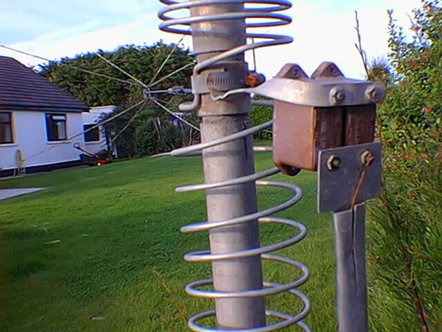
I wound a coil of about 24 turns, using a plastic rainwater down spout as a coil former (about 4ins diameter) , and slipped it over the vertical. I tapped the coil about 8 turns back from one end, and assembled the whole shebang as shown in the following drawing and photo... They say a picture is worth more than a thousand words.....Sooo!!!
I got a pair of capacitors which were marked as being 100pf each. I mounted these in parallel as shown in the pics.When I measured their value using the MFJ SWR analyser, the value at 3.6mHz was 250pf. Having got the antenna raised to the vertical position, I guyed it with three lengths of nylon twine.
I next connected my trusty MFJ SWR analyser, and the battle commenced. By tapping the coils with the fly leads, and moving the hoseclips up and down , to stretch, or compress the coils , I eventually got resonance on 80m and 40m.The SWR was about 1.5:1 on 80m, and a bit better on 40m.
This L/C assembly should cope very well with whatever overall length that you find convenient. Mine certainly coped well with lengths varying between 25ft and 40ft. When I built the final version of 40ft overall. The top coil was redundant, and the bottom coil was smaller as well.
My ground plane consists of 32 lengths of wire, 60ft each, and another 4 lengths of about 120 ft each . These are buried about 2ins deep in the lawn. I am situated on the side of a hill, about 175ft ASL. The sea is about 1 mile away, and on three sides of the QTH. This is a very good site for radio, and this vertical has worked a lot of DX for me.

Cheap and cheerfull 160M addition
I also fired it up on 160M, using a thirty turn, 4inch diameter coil, in parallel with a 400pf capacitor mounted below the 80M coil. It worked as well as one might expect under the circumstances, but was very narrow-banded, and not very efficient. I found a big improvment in performance by using the HF2 as a support for a 160M inverted L.. I used a 400pf capacitor at the feed point of the antenna, in series with about 140ft of wire, rigged as shown in the drawing. I pruned the wire length until it was resonant on the desired frequency.
The other option would be to use a fixed wire length, and a 500pf variable capacitor. This would allow you to tune anywhere in the band.

Home Links Contact Information
Copyright © 1995 - 2021 John Tait All rights reserved.
All pages and content there-in, are the intellectual property of the author, and protected by law.
All pages and content, are subject to change at any time, without notice.