The Motorola Radius GP300 VHF or UHF handheld transceiver has a dedicated signal port
on its back for programming it. Lots of info on that subject can be found on the web,
but although the circuit wasn“t complicated, I didn“t find a PCB layout for it. I also
wanted something to connect the RIB to the GP300 in a fast and easy way. What I present
here is the result of my work on this.
The circuit is just a RS-232 to TTL adapter. Since the data port on the GP300 is bidirectional, a 7407 driver is used to control the data from PC to radio and from radio to PC. Since the battery must be removed to access the programming port, the circuit should also provide 7.5V to the walkie. That“s why I included the shunt regulator and the 1N4148 diodes:
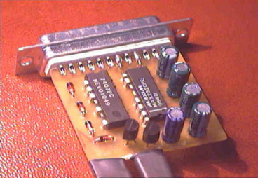
And here is the PCB:
If you have any doubt about the circuit, this picture could help:
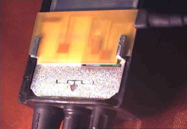
As I said, I also wanted something to connect the radio to the RIB easily. To prevent dangerous shorts, isolating lacker must be applied to the PCB, everywhere but over the contacts:
This is what it looks like while attached to the back of the GP300:
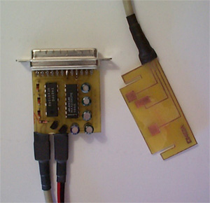
The final, wired product of your work should look similar to this:
My RIB worked from the first time. I didn`t include any LEDs in the circuit because they are not needed and I“ve had problems because of them before. Sometimes, the available current on the data bus is not enough to light the LED and keep the minimum signal levels.
I can`t help you if you need the Radio Service Software.
You can get it from a Motorola dealer.