I finally designed a PCB for a battery charger described in the datasheet for the MAX712/MAX713 fast charge controllers. The only difference between them is the battery-fully-charged sensing method. The MAX713 is designed for NiCd batteries, while the 712 is for NiMh batteries. Read the datasheet for details. Everything you will need to know is already there:
MAX712/713 Datasheet (PDF Format)
You will need to read carefully the above linked datasheet in order to complete this project. The guys from Maxim explain there how to choose the values for some of the components included in the circuit. Those values vary depending on the number of cells of the battery pack you intend to charge and the charging time you want to set.
Notice that if you power the charger with only 12V, it won�t be able to charge packs with more than six 1.2V cells (7.2V). If you try to charge something bigger than that from 12V, the MAX will get hot and the charging current won�t be what expected from the value of the sensing resistor. This is because the IC will sink as much current as possible from the base of the power transistor, trying to get the voltage drop on the sensing resistor up to 250mV. This won�t be possible because of the voltage drops across that transistor and the diode. The charging current won�t be as high as expected. To confirm this, just check the tension on the sensing resistor. Everything is explained in the datasheet. My MAX712�s haven�t died yet, but they get hot from time to time...
Here is the PCB view (as seen from the tracks side, maybe you'll need to mirror it prior to printing...):

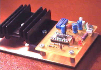
I've built several of these chargers for different NiCd and NiMh battery packs. They work great, as expected from the reading of the datasheet. The only problem I had once was the current needed to supply power the charger. This circuit supplies current to the battery in a linear way. If you want a higher charging current, you'll have to study the datasheet, and look for the switching charger (much more efficient). At Maxim they also have interesting application notes on this ICs. Here is how one of my chargers looks like, next to the heatsink for the power transistor:
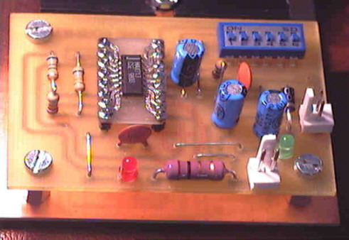
This is a closer look to the circuit board. You can see that I used the SMD version of the IC and inserted
it in the circuit with the aid of a small PCB with DIL pins, although
another solutions would do the trick. If you get a DIL IC, just bend the pins to the outer side a bit.
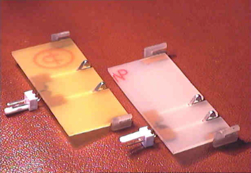
This is how they look attached to the batteries:
|
|
|


I hope this gives you some ideas for conecting the charger to your battery packs.