![]()
(Proyectos de transceptores)
Note: The following projects were gathered from the internet, therefore the author does not endorse any of the projects, they are on your own risk.
(Nota: Los proyectos siguientes se recogieron de internet, por consiguiente el autor no garantiza ninguno de los proyectos, ellos son bajo su propio riesgo.)
|
2N2/20 - A 20 Meter,
Discrete Component CW Transceiver Built Manhattan-style
Designed by:
Jim Kortge, K8IQY
|
|
Summary The 2N2/20 is the latest incarnation of the rather long list of 2N2/XX designs. Departures from 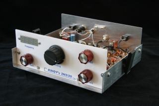 the all "2N2222 transistor dictate" provided an opportunity to use a
variety of discrete semicondutors to enhance performance. Within the
IF chain, MPSH10 transistors were used, a J176 FET was used in the
audio mute for very clean QSK keying, and a 2SC2166 final amplifier,
used in the transmit strip allows the rig to put out about 7- watts.
Commercial DBMs were also used to make construction easier for the
beginning builder. Another departure from other 2N2/XX designs was
the use of a commercial frequency display (KD1JV product) to show
the operating frequency.
the all "2N2222 transistor dictate" provided an opportunity to use a
variety of discrete semicondutors to enhance performance. Within the
IF chain, MPSH10 transistors were used, a J176 FET was used in the
audio mute for very clean QSK keying, and a 2SC2166 final amplifier,
used in the transmit strip allows the rig to put out about 7- watts.
Commercial DBMs were also used to make construction easier for the
beginning builder. Another departure from other 2N2/XX designs was
the use of a commercial frequency display (KD1JV product) to show
the operating frequency.This rig features a Norton "Noiseless feedback" RF Amplifier, electronic RF gain control, RIT, 6-poles of crystal filtering with a 500 Hz bandwidth, and 100 KHz of band coverage from a voltage tuned, stable VFO. The debut of this transceiver was at Pacificon 2004, hosted by NorCal, and held in San Ramon, CA over the October 10th weekend. Slightly updated versions of this presentation were also given at Atlanticon in March, 2005, and again at Ozarkcon in April, 2005. The latest version of the presentation is available in .PDF format on this page, along with other pertinent information about this rigs design, construction, and performance. |
 |
| The 2N2/20 follows the
general design of many QRP rigs. It consists of a superheterodyne
conversion strip (upper row of blocks) on the receive side and a
complete RF generation strip (lower row of blocks) on the transmit
side. Both sections share a common VFO. Each of these subsystems
contains a Local Oscillator (LO). The receive LO allows one to
optimize receiver response by centering the receive pass band to the
center of the crystal IF filter. On the transmit side, a separate LO
provides offset adjustment, resulting in a side tone matching the
received audio. Switching between receive and transmit is done with
solid-state switches to provide QSK capability. When transmitting,
the 2N2/20 is listening to its own signal. |
| 2N2/20 Schematic
Diagrams |
 |
|
Receiver front-end from the
signal pickoff after the transmit low pass filter to the output
from the diode DBM.
|
 |
|
VFO using varicap diode tuning. The two
outputs drive the receive and transmit mixers.
|
 |
|
Receive strip from input to the
post-mixer amplifier to output from the IF amplifier.
|
 |
|
Receive strip from input to the roofing
filter to output from the first audio amplifier.
|
 |
|
Receive strip from input to the receive
mute to output from the main audio amplifier.
|
 |
|
Transmit strip from VFO signal input to
the transmit mixer to output from the Cascode amplifier.
|
 |
|
Transmit strip from input to the driver
amplifier to output from the transmit low pass filter.
|
| 2N2/20
Construction Pictures |
Follow down this page to see how this rig was constructed! |
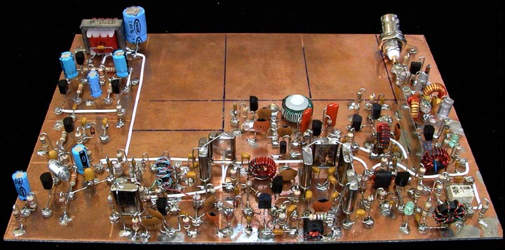
The 5 X 7 inch substrate is partitioned
off as shown. In general, each stage is built within the defined
areas.
|
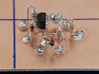
Construction on this rig started with the receiver T/R switch which is also part of the front-end gain control system. The parts for the gain control function were added when the control for that capability was built and installed. |
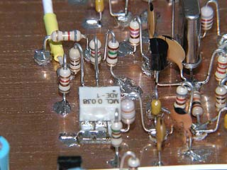
Next, the receive input bandpass filter parts were added. Polystyrene capacitors were used as those were available in the junk box. Any NPO disc ceramic or monolithic ceramic capacitor could be used here also. |
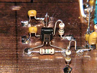
This is the first version of the receive RF amplifier, which was a conventional, grounded base configuration. It was later abandoned after determining it produced excessive noise and replaced with a Norton "noiseless feedback" amplifier. That amplifier configuration is shown in the next picture. |
Surprisingly (and fortuitously), all of the pads that were needed for the above amplifier configuration were also needed for the Norton design shown here. That made rebuilding this stage very easy. In fact, a number of parts were of the same value and were retained in their original positions. |
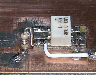
A MiniCircuits ADE-1 level 7 mixer was soldered to its own substrate, and that in turn glued to the main substrate. Connections to the mixer were then added. Note: Minicircuits is discouraging the purchase of this mixer in small quantities by charging a very high price for one or two units. An alternative is to purchase the SCM-1 mixer that is essentially identical in performance and about one-third the cost of an ADE-1. |
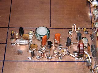
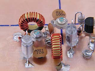
The VFO circuitry was added next, so that the front-end of the receiver could be tested. The VFO main inductor (green wire) is mounted to the substrate with a pair of #8 nylon shouldered washers and a 4-40 nylon screw. Installed between the VFO and the RF amplifier is a shield made from thin, tin plated steel stock obtained at a hobby shop. |
Next, the receive post-mixer amplifier components were added. This stage took additional development time to get it matched to the crystal filter correctly. |
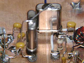
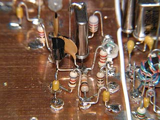
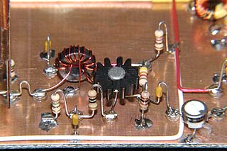
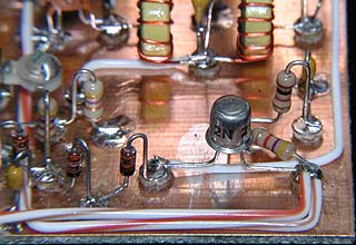
After the post-mixer amplifier was working correctly, the 4-pole main crystal filter was added. The crystal cases are grounded to maximize performance, and that also adds mechanical stability to the elements. The binocular core in the foreground is the input transformer to the IF amplifier stage. |
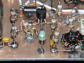
The receive IF amplifier uses two transistors in a common base-common emitter configuration. MPSH10 transistors were required to achieve the desired stage gain of 40 dB. PN2222 transistors were tried, but those ran out of gas well before the desired gain was achieved. |
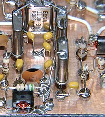
After the IF amplifier, two crystals and their associated components were added to complete the roofing filter. Again, the crystal elements were grounded. The 33 Ohm resistor used to terminate this filter can be seen to the far left. |
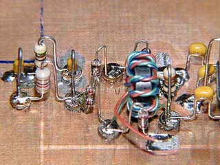
Components to create the product detector were next added. The trifilar transformer was wound using kynar insulated wire wrap wire in three colors, readily available at Radio Shack and many other sources. It's a bit slippery to handle, but works well overall. The unterminated lead in the foreground will be connected to the local oscillator output in the next step. |
Next, the receive local oscillator was built. The lead from the product detector above is now attached to the output low pass filter of this stage. With an outboard audio amplifier connected to the output of the product detector, the receiver could be used to listen to signals on 20 meters. |
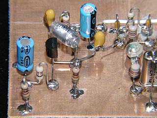
Completing the build along the front edge of the board is the receive audio preamplifier stage. The large 3300 pF polystyrene capacitor in the middle of this image could be replaced with a much smaller mylar or monolithic ceramic capacitor. It was used because it was available. |
At 90 degrees clockwise from the previous picture, the receive audio mute components were added. Missing is this image are the two germanium diodes which limit the audio level reaching this stage. Those were added later. |
Completing the build along the short side of the substrate and also the completion of the receive strip are the components of the two-stage main audio amplifier. This stage can drive earphones or a speaker to volume levels far above those needed for comfortable listening. The volume control potentiometer will be connected to the rightmost pad shown in this image. |
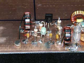
Completed receiver before rebuilding the receive RF amplifier. |
| 2N2/20
Construction Pictures - (continued) |
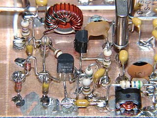
The transmit strip began with the construction of the transmit local oscillator. This circuitry is positioned inboard of the product detector. |
Next, the circuitry for the transmit mixer was added. The white coax coming in from the top of this image carries the VFO signal to this stage. |
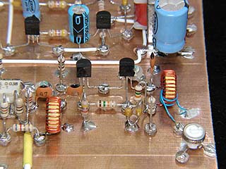
Looking from the opposite direction, one can see the two stage cascode RF amplifier components. The input tuned circuit is on the left with the output tuned circuit being on the right. A 50 Ohm trimmer controls the power level to the driver stage which was built next. |
Components for the driver stage were then added. The 2N2222A uses a finned heat sink to keep it cool. This view is from the back of the substrate; the cascode amplifier just shown is to the right. |
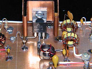
Shown here are the final amplifier and output low pass filter components. The heat sink on the 2SC2166 transistor was replaced when the completed board was packaged. This view is from the front of the substrate; the driver stage just shown is to the left. |
Completing the transmit strip are the few components which make up the receive/transmit switch. This single transistor stage causes the 2N2/20 to transmit when the key is pressed, and at the same time attenuates the input to the receiver. It also does the shaping of the keying waveforms. |
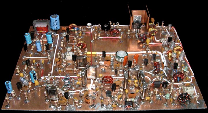
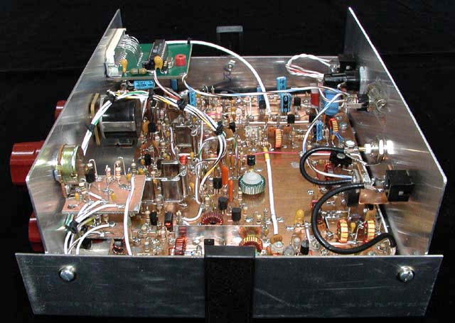
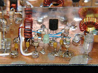
Completed 2N2/20 before rebuilding the
receive RF amplifier, and adding the board mounted RIT
components.
|
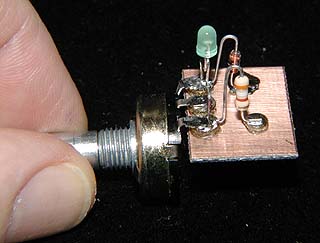
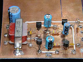
Before packaging the rig, two additional control modules had to be built. This is the receiver RF gain control module which is constructed on a small piece of PC board material. It mounts to the front panel using the potentiometer threads. Only dc voltages are controlled by this module. |
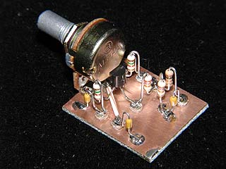
In a similar format, the receiver incremental tuning (RIT) control module was built. It too only provides dc voltages to the controlled circuitry. Those parts are mounted on the main substrate adjacent to the VFO. This module version was built using all leaded components; the one for the 2N2/30 is all surface mount components. |
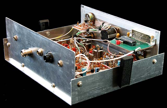
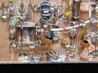
One of the items not shown in detail is
the use of a KD1JV display module to read out the operating
frequency. That module is in the upper right of this image. Its
input is connected to the VFO line driving the transmit mixer
and coupled through a 2 pF ceramic capacitor. Similar modules
are also available from AADE. Both vendors can be found on the
web.
The RIT and RF gain modules, mounted to the front panel, can be seen on the upper left in this image. Rear panel connectors from left to right include: key, antenna, power, and audio. Adjacent to the power connector is a fuse holder. |
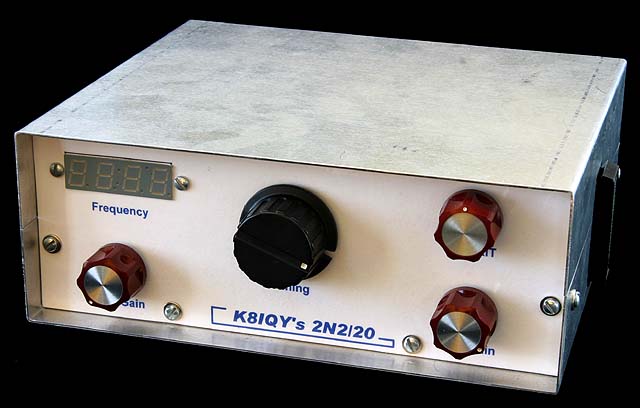
One last image of the rig showing the
front panel controls. Beginning at the left: audio gain, tuning,
RIT (upper) and RF gain (lower).
The two-piece case was bent on a 12 inch Harbor Freight brake/shear from 0.040 inch 6061 T6 aluminum sheet stock. Lettering was printed on plain white paper, which was then affixed to adheasive backed transparent film. The edges of the film wrap around the edges of the front panel, and the controls keep the "sandwich" tight against the panel face. |
| 2N2/20 Parts |
 |
 |
 |
![]()
_________________________________________________________________________________________________________________________________________________________
by K9GDT

The “Wheat Box”

Why not? It’s no secret that SSB and CW are more effective when the going gets tough. I operate those modes, too. I enjoy AM operation because it sounds so good!Also, the folks who operate AM are typically a friendly and courteous bunch, willing to share their considerable technical expertise with fellow hams.
![]()