
MAGNETIC LOOP for 40 and 80 mts.
by VK3YE (ex VK1PK)

Description
Able to
cover all frequencies between 3.5 and about 10
MHz, the loop described here is directional,
does not require a radial system, and stands
just 1.8 metres tall. Most parts needed can be
purchased at a hardware shop. The antenna can be
put together in an afternoon and requires only
hand tools to assemble. It should cost less than
sixty dollars to build.
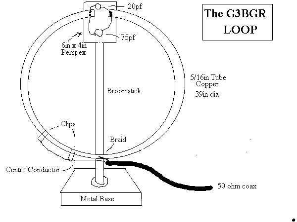
Shown below is the schematic diagram for the
loop. Note that the element is continuous except
for a gap at the top across which the variable
capacitor is wired. The feedline is connected to
the bottom of the loop. Also shown is the
physical construction of the antenna. The loop
element is 1.5 metres square and is supported on
a wooden cross. To minimise losses, thick
aluminium strip is used for the element. At the
top of the loop is a high-voltage variable
capacitor. This is used for adjusting the
antenna to the operating frequency. Because of
its narrow bandwidth, the tuning is very sharp
and a vernier drive has been added to make
tuning easier. Dimensions are not particularly
critical, provided it is possible to bring the
loop to resonance on all operating frequencies
with the variable capacitor used.
Parts
needed
The following materials are required to build
the antenna:
- 3 2m lengths of 3×20mm aluminium strip
- 1 1.8m length of 20×44mm pine
- 1 1.5m length of square (12×12mm) wood
- 1 polyethylene chopping board (medium or large size)
- 1 150 x 80×4 mm piece of stiff high-voltage insulating material (eg bakelite)
- 2 right angle metal brackets
- 1 20-400pF high voltage variable capacitor
- 1 6:1 vernier reduction drive (Dick Smith No P-7170)
- small length of coaxial cable braid
- RG58 coaxial cable (any length) and PL259 plug
- screws, nuts and miscellaneous hardware
Many of the above items
can be bought at hardware shops. The main
exception is the wide-spaced variable capacitor.
These are almost unobtainable commercially,
though you could try Daycom in Melbourne. Other
possible sources include old high power
transmitting equipment, hamfests and deceased
estates. The exact value of the variable
capacitor is not particularly important,
provided it is at least about 400pF. The
capacitor used in the prototype was a two gang
200pF unit with 2mm spacing between the plates.
The gangs were connected together to provide the
needed maximum capacitance.
If your attempts to obtain a suitable capacitor
fail, there is always the possibility of making
one. Full construction details appear in DK1NB’s
magnetic loop design program (details later).
Construction
The first step in assembling the loop is to make
the wooden cross that supports the aluminium
element. This is done by bolting a 1.5m
horizontal cross piece to the 1.8m vertical
section. A white polyethylene chopping board is
used for the antenna’s base. The two
right-angled brackets are used to attach this to
the vertical section. The next step is to bend
the three lengths of aluminium so that they form
a 1.5 metre square loop able to fit on the frame
when bolted together. As is visible in Figure
Two, two pieces are “L” shaped, while the other
is bent into a shallow “U”. Note that the two
L-shaped pieces are about 10cm apart at the top
of the loop. These are physically joined by the
bakelite insulation block that is attached to
the top of the length of pine. The upper
L-shaped pieces meet with the lower U-shaped
piece at points ‘v’ and ‘w’. The overlap is
about 40-50 millimetres. Make the electrical
connection at these points as good as possible.
To achieve this, sand the aluminium at the point
of contact and use two or more small bolts to
hold the pieces together. Use special conductive
paste if available.The variable capacitor is
mounted on a home made metal bracket so that its
shaft faces downwards. To the shaft is attached
a vernier reduction drive. Use either small
brackets, fishing line or glue to fasten the
frame of the reduction drive to the 1.8 metre
vertical section. Note the thick, low-resistance
conductors between the end of the loop and the
tuning capacitors. Braid from a length of
coaxial cable was used in the prototype. Make
these connections short to minimise losses.
The loop is fed at the bottom. The braid of the
feedline connects to the centre of the lower
horizontal element (see diagram, point ‘x’). The
inner conductor connects to the loop at point
‘y’ via a 900mm length of coaxial cable (inner
and braid soldered together). At both ‘x’ and
‘y’, a small bolt, nut and eye terminal
connector is used to make connections to the
aluminium element. The distance between ‘x’ and
‘y’ and the length of the coaxial cable may both
have to be varied for proper matching – this is
discussed later.
Adjustment
The object of the adjustment process is to
adjust the section between ‘x’ and ‘y’ until the
antenna’s feedpoint impedance can be made to
equal 50 ohms on the bands of interest. The
first step is to connect the antenna to an HF
receiver tuned to 7 MHz. Set the receiver’s RF
and AF gain controls to near maximum and the
antenna’s capacitor to minimum capacitance
(plates fully unmeshed). Then gradually increase
the capacitance. Not much will happen at first,
but the noise from the receiver should gradually
start to increase. Further adjustment of the
capacitor will result in the received noise
falling. Turn the capacitor back to the position
where the noise peaks. Depending on the value of
your capacitor, the plates should be around a
quarter meshed at this point. This test confirms
that the antenna can be tuned to 7 MHz.
Repeat the process for 80 metres. This time, the
noise should peak when the capacitor is near
maximum capacity. If it is not possible to
obtain a peak, try setting the receiver to a
higher frequency (4 or 5 MHz) and tune for a
peak. If a peak is obtained there, but not on
3.5 MHz, it is likely that the variable
capacitor’s maximum capacitance is too low for
eighty metres. Possible remedies include
substituting a larger capacitor, connecting high
voltage fixed capacitors in parallel with the
variable capacitor or making the loop
larger.Having confirmed that noise peaks can be
obtained on all frequencies of interest, it is
now time to ensure that the antenna’s impedance
is 50 ohms at these frequencies. This entails
making adjustment to the antenna’s feed pont.The
use of a resistive antenna bridge is recommended
so that you can make antenna measurements
without radiating a signal. If all you have is a
conventional SWR bridge, make adjustments during
the day to minimise the risk of interference to
other stations. Position the antenna near its
final operating position (which should be out of
other people’s reach). Set your transceiver to
about 3.580 MHz. Adjust the variable capacitor
for maximum received noise. Transmit a steady
carrier and note the reflected power or SWR.
Adjust the transmitter up and down 40 or 50
kilohertz to find the precise frequency where
the SWR is lowest. Note the reading at this
frequency. If you are lucky, the reflected power
should be nearly zero. Otherwise, adjust the
length and position of the 900mm lead joining
the feedline to point ‘y’ and/or the spacing
between points ‘x’ and ‘y’. You will find that
there is some interaction between these
adjustments and the setting of the variable
capacitor.
Every time a change has been made, adjust either
the transmitting frequency or the antenna’s
variable capacitor for the point where reflected
power is lowest. Repeat these procedures until
reflected power is either zero or close to it.
When making these adjustments, there is a
temptation to leave the transmitter keyed while
making changes to the antenna or adjusting the
variable capacitor. This should not be done for
two reasons. The first is that the voltages at
the top of the antenna element can be quite high
(hundreds or even thousands of volts) even with
quite low transmitting powers. The second is
that the loop is detuned when people are near
it. Thus any adjustment made when you are near
the loop will not be optimum when you move away.
This effect is particularly pronounced on higher
frequencies, and applies to metal objects as
well as humans.
Once a length and position for the 900mm coaxial
cable has been found, along with an appropriate
spacing between ‘x’ and ‘y’, all further
adjustments can be done with the antenna’s
variable capacitor. Operating the antenna is
described in the next section.
Operation
The Q of this antenna is very high. This means
that it can only operate efficiently over a
narrow frequency range (5-10 kHz typical).
Almost every time you change frequency, you will
have to change the setting of the variable
capacitor.
As mentioned before, this is done by peaking the
capacitor for maximum received noise at the
desired operating frequency. If the reflected
power is high, make further adjustments until it
is acceptable. Again the use of a resistive-type
bridge (rather than a conventional SWR meter) is
preferred because of the ability to tune up
without causing interference.
Note that the loop is directional, with a sharp
null when the element is facing the direction of
the incoming signal. This makes its behaviour
different to that of full-sized quad elements,
where the null is off the sides of the loop.
This directivity can be useful when nulling out
interference. It is also useful to remember when
other stations report difficulty in hearing you
– turning the loop may improve your signal.
Results
This loop has been used extensively on eighty
metres. Most contacts have been made with the
antenna indoors. Though performance is well down
on a dipole, contacts into Western Australia and
New Zealand have been made with it. The power
used was twenty watts. Lower powers have been
tried, but results have not been good. Contests
are always good events to test the effectiveness
of new antennas. During July 1997’s hour-long
3.5 MHz Australasian CW Sprint, twelve contacts
were made with the loop. This was despite the
added handicap of having to retune the antenna
with every significant frequency shift.
As would be expected, the loop’s disadvantage
when compared to full-sized antennas falls with
increasing frequency. On 7 MHz for instance, the
theoretical difference between the loop and a
half-wave dipole is barely one s-point. Tests
have confirmed the effectiveness of the loop on
40 metres, though all contacts have so far been
within VK/ZL.
Improving the loop’s efficiency
The antenna
described is capable of good results on 80, 40
and probably 30 metres. However, it is a
compromise, designed for low cost and easy
construction with basic tools. Doing any of the
following will increase its efficiency and/or
usefulness.
1. Use copper rather than aluminium. Copper is
more conductive (but more expensive) than
aluminium. This means that a version of this
antenna using copper rather than the specified
aluminium is likely to be more efficient than
the prototype. Copper water pipe (the thicker
the better) should be suitable.
2. Soldering the loop element directly to the
variable capacitor will also improve performance
and long-term reliability, especially if the
antenna is used outdoors. The reason why this
wasn’t done in the prototype was due to the
difficulty in soldering to aluminium.
3. Use a single piece of metal for the conductor
to reduce resistive losses. Where this is not
possible, either solder/weld pieces together, or
use conductive paste to minimise losses.
4. Make the loop a circle or octagon instead of
a square. Square loops are the easiest to make,
but cover less area for a given perimeter than
other shapes. This lowers efficiency.
5. Make the antenna rotatable. The loop’s deep
nulls can be used to advantage in nulling out
interference from power lines, TV sets and other
stations.
6. Use a larger loop. Efficiency increases
rapidly with loop size. Even a 2 or 2.5 metre
square loop should be noticeably more efficient
than the 1.5 metre antenna presented here. The
use of magnetic loop simulation software (see
elsewhere) allows one to estimate the
improvement possible by making this and other
changes suggested above.
7. Use more reduction on the variable capacitor
to make adjustment easier. The first prototype
had only one vernier drive on the capacitor’s
shaft. With this arrangement, getting the
antenna tuned to the desired frequency was
tedious because the tuning is sharp. If you
routinely change frequency, a second drive is
well worth the cost, particularly if 40 and 30
metres are the main bands of interest.
To perform this modification, install the two
vernier drives in tandem, as shown in Figure
Two. If the front drive contains a 0-100 dial,
you may find that the knob is limited to three
turns and the back part restricted to 180 degree
rotation. To overcome this, remove the knob,
unscrew the 0-100 dial, and remove the c-shaped
bracket that is restricting movement.
![]()
___________________________________________________________________________________________________________________________________________________________