Digital Interface v.II.2
Integrated K2/100 Set-up


OVERVIEW

Those of you who have read the COMMENTS and NEW IDEAS, NEW SET-UP paragraphs I have posted on the Technical Info and Schematics page of my Digital Interface, know that the v.II.2 of my PCB, because of lack of room, cannot coexist within a Basic K2 which has either the KDSP2 or the KAF2 and KBT2 options installed.

You also know that I have managed to find what I think is the most suitable place to implement it on the integrated K2/100 set-up.

I have also introduced an optional modification when installing the DI board. It consists in getting the received AF from pins #1 and #2 at P2 on the KDSP2 or KAF2 boards, instead of getting it from J5 at the RF board, the auxiliar AF connection. In this way the user may take advantage of the K2's filters features for his/her digital contacts.

The following pictures show how I figured the PCB construction and installation:

K2/100 Digital Interface already assembled and ready to be installed.

Please notice the right-angled polarized connectors and the position of C5, the 220 µF capacitor, which help to get a low profiled device.

Click on the thumbnail to view the enlarged picture

This image shows the placement of my K2/100 Digital Interface on the KPA100's Internal shield (without the side grounding clips present on later versions).

Click on the thumbnail to view the enlarged picture

This is a side view of the above installation with the DI board fastened to the KPA100 internal shield.

Notice that there are no nuts securing the fastening screws, as I threaded the relative mounting holes at the shield. Thus there is no need for the shield to be removed, should you need to remove or reinstall the DI PCB.

Click on the thumbnail to view the enlarged picture

Same set-up with the KPA100 already installed on top of the K2 to conform the integrated K2/100, as seen from the left side angle.

Click on the thumbnail to view the enlarged picture

This image shows the modified KDSP2 P2 3-pin male header. I substituted 2 of the standard pins (#1 and #2) of the P2 3-pin male header for 2 longer ones so that, once the header is soldered, I get the expected normal lenght 3 male pins on the bottom side of the KDSP2 (or KAF2) board, to be plugged to J2 at the control board, while I also get 2 male pins on the top face of the KDSP2 (or KAF2) board, to be used to connect the cable that feeds the filtered received AF signal to J4 at the DI v.II.2

Click on the thumbnail to view the enlarged picture

This picture shows the 2 pin female housing end of the cable that feeds received AF to the Digital Interface v.II.2 J4 3 pin male connector from P2 at the KDSP2 board.
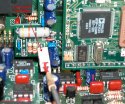
Click on the thumbnail to view the enlarged picture

New

CONSTRUCTION MANUAL

A revised construction manual is available for downloading at my Downloads page.


AVAILABILITY

I still have a small stock of this PCB for those of you that might be interested in getting one. If you are, please contact me. Thank you.


Pictures Gallery

DOUG FAUNT's, N6TQS, K2/100 Digital Interface set-up.

Click on the thumbnail to view the enlarged picture Click on the thumbnail to view the enlarged picture Click on the thumbnail to view the enlarged picture

The above pictures are published by courtesy of Doug Faunt, N6TQS.
Many thanks Doug !.

THE T33 VENTURE

Doug installed my v.II.2 Digital Interface in both his two integrated K2/100 rigs, which he took with him to the Banaba DX-pedition 2004. The alloted DX-pedition call sign was "T33C".

Banaba (T33) is a Micronesian island that is part of the Republic of Kiribati, in the Pacific Ocean.

The T33C operation including all individual callsigns was approved for DXCC.

The 22 members of theT33C team, including 19 operators, came safely back from Banaba Island. The DXpedition to that "most wanted" entity in the Central Pacific made 75,000 QSOs between April 4 and April 15, 2004 with amateurs throughout the world. This was the first operation from Banaba since 1999.

Should you be interested in getting more details about this event, please visit the Banaba DX-pedition 2004 official website.

BTW, Doug's current version of the miniDIN connector's pin set-up is compatible with the data connectors on his ICOM's IC706MKIIG and Yaesu's FT817.

Last updated on June 13, 2005.

Click to go top

Valid HTML 4.0!