|
THE HIGH - EFFICIENCY
MULTIBAND
DESIGNED AND SERIES MANUFACTURED BY DL6QA |
TECHNICAL DATA
|
Frequency range: |
13.5 - 29.7 MHz, continuously tunable |
|
Power rating: |
all modes max. 100 Watts |
|
VSWR: |
better than 1.1 : 1 at resonant frequency |
|
Shape / Dimensions: |
square
/ approx. 87 x 87 cm |
|
Area enclosed by loop: |
approx. 0.76 square meters |
|
Antenna material: |
|
|
Antenna weight: |
approx. 5 kg only, excluding control unit |
|
Polarization: |
vertical if installed in vertical position |
|
Directivity: |
bi-directional
(figure eight radiation pattern if installed vertically |
|
Radiation
angles in |
simultaneous full bi-directional coverage of all elevation angles from almost 0 to 90 degrees providing the function of both a vertical antenna and an horizontal dipole antenna. |
PRIME ADVANTAGES
|
- exceptional high-efficiency performance |
|
- extremely low VSWR |
|
- small and handy size |
|
- numerous application possibilities |
|
- quick and easy installation at virtually
any place |
|
- easy-to-operate |
|
- multiband frequency coverage including
split operation (all modes) |
|
- vertically polarized bi-directional radiation pattern |
|
- radiation of magnetic field |
|
- considerable reduction of TVI / BCI |
|
- high suppression of transmitter harmonics |
|
|
|
- radials or counterpoise not required |
|
- antenna tuning unit (ATU) not required |
|
- remote tuning control unit mains independent
(field-day operation) |
|
- most suitable for indoor operation as well |
The QAM-Loop (DL6QA –Magnetic Loop ©) has mainly been designed for those users who do not have any possibility or sufficient space to install a multiband transmit / receive antenna or live in an area with antenna restrictions or who prefer inconspicuous respectively concealed operation.
RADIATION PATTERN OF THE QAM-LOOP
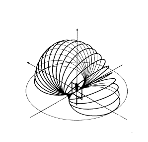 The "null" of the loop is perpendicular to
the plane of the loop.
The "null" of the loop is perpendicular to
the plane of the loop.
A magnetic loop generates a magnetic field by producing as high a current as possible in the resonant circuit. The intensity of the magnetic field is strongest when it leaves the loop and falls off rapidly as it moves away from the source. It propagates through objects much better than electric fields do and thus a magnetic loop can also be operated indoors inside buildings.
The electric component of a radio wave is induced by the presence of the magnetic field and the energy associated propagates through space. The intensities of both the magnetic and electric fields assimilate when they move away from the source and are about equal at approx. l / 6.
LOOP EFFICIENCY OF CIRCULAR AND SQUARE MAGNETIC LOOP
|
In far more than 90 % of all articles concerning efficiency of magnetic loops, you will be misled to believe that the efficiency of a square loop is much inferior to the efficiency of a circular loop. This, however, only applies to all cases where the loop conductor of a square and circular loop have the same length. But such articles mislead thoughtless readers. The reason is that most writers copy from each other. Not the shape of the loop is decisive but the radiation area. There is no noticeable difference in the efficiency of a square, circular, octagonal or triangular loop if you compare identical radiation areas. But the effective conductor length of a square loop is approx. 13 % longer in comparison to a circular loop of same radiation area. If you compare the efficiency of a square and circular loop of same radiation areas in the diagram you will note no "remarkable" difference in efficiency. Area of each individual loop = 0.75 square meters Y-axis = frequency in MHz X-axis = efficiency in % Quadrat = square loop (data of QAM-Loop, 87 cm x 87 cm, edition 1994) Kreis = circular loop |
 |
FIRST PROTOTYPE OF THE QAM-LOOP "BLACK MAGIC" (March 1993)
 Frequency range: 13.5 MHz to 29.7 MHz continuously
tunable.
Frequency range: 13.5 MHz to 29.7 MHz continuously
tunable.
The magnetic loop shown in this photo was designed for indoor operation only and was the basic design for later series production in small lots. The performance of the "Black Magic" was tested in extensive trials over a period of several months. The results were exceptionally satisfying being able to work all continents in CW using a Kenwood TS-450 and an indoor antenna. Later on the antenna was modified for temporary operation on 7 MHz or 10 MHz bands by applying an additional individual plug-in fixed capacitor depending on frequency range.
Even though the circumference of the QAM-Loop is much too short for effective intercontinental DX operation on the 7 MHz or 10 MHz bands (rather poor efficiency) I managed to work various DX stations on these bands in 1998 with an indoor operated modified series type version of the QAM-Loop (identical size as the "Black Magic" 87 x 87 cm). This was in the early beginning and ascent of sunspot cycle No. 23. Among the DX contacts were e.g. WL7VO of Chicken / Alaska and HL5XF of Ulsan / Korea (both on 10 MHz and confirmed by QSL). My signal reports were 559. This proves the high-efficiency and optimum design of the basic version of March 1993.
CALCULATED LOOP POWER EFFICIENCY OF THE QAM-LOOP (Power
Rating 100 W)
|
Frequency |
Efficiency |
|
14 MHz |
88
% |
|
18 MHz |
95
% |
|
21 MHz |
97
% |
|
24 MHz |
98 % |
|
29 MHz |
99
% |
Computations are based on the article "SMALL HIGH EFFICIENCY ANTENNA" by Ted Hart, W5QJR.
VARIOUS MAGNETIC LOOP ANTENNAS DESIGNED BY DL6QA
All photos unless mentioned provided and © by DL6QA.
 |
1992 (designed January 1992) Octagonal magnetic loop. My first high-efficiency and DX approved magnetic loop antenna for indoor operation. Frequency range 14.0 MHz to 29.7 MHz manually tuned. Power rating max. 100 W. Conductor is made of copper pipe 22 mm diameter. Based on the W5QJR Hart loop concept. A lot of professional know-how and skill are required to build effective high-efficiency magnetic loop antennas. Don't try to duplicate a loop if you are a home constructor with two left hands. The result will be very disappointing. Construction is not a single weekend job. |
 |
1992 Close-up view of high voltage variable split stator (butterfly type) tuning capacitor of octagonal magnetic loop. Voltage rating approx. 4 - 5 kV peak voltage. Variable capacity 3 to 55 pF. The residual starting capacity must be as low as possible.
|
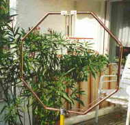 |
1992 Octagonal magnetic loop as mentioned above. Magnetic loops are the best solution for those having to settle for an indoor antenna because of legal, social, family, green neighborhood or landlord reasons but nevertheless wish to participate in effective DX amateur radio communications. |
 |
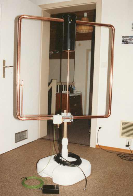
1993 First series type QAM-Loop © for outdoor / indoor operations. Note the gamma match without reactive component. The space of the copper tubing of the gamma match between the horizontal and vertical portions of the main 28 mm diameter loop conductor are slightly different (patents pending). The optimal positioning of the gamma match for series production ( reproduction of specifications) was a very time consuming engineering expenditure over several months but now contributes to the very exceptional high performance of the QAM-Loop. I have also combined two separate QAM-Loops on a common boom, called the "GEMINI" but this configuration was too bulky and too work intensive. The GEMINI configuration was tuned by two separate loop controllers. |
 |
1993 First prototype monoband QAM-Loop for 7 MHz operation. |
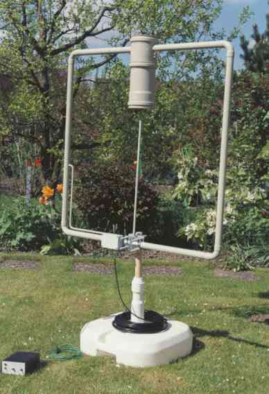 |
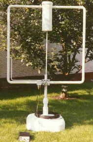
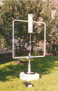
1994 Final series type QAM-Loop for outdoor / indoor operation. See above technical data. For special applications this configuration can be temporally modified for operation on two additional frequency ranges to 7 MHz or 10 MHz by adding an external adapter enclosing two separate additional fixed capacitors. However, the main loop conductor in this case is much too short to expect high efficiency operation (10 MHz = 14 %, 7 MHz = 4 %). The antenna has an incorporated ventilation system via the gamma match to avoid accumulation of humidity in the water-tight tuning compartment. |
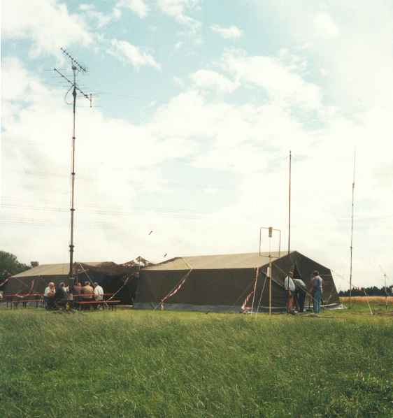 |
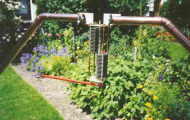
1996 Field-day of ILLER VALLEY local amateur radio association, district DOK T16 of the DARC. Assisted by Bavarian Red Cross of Weissenhorn. QAM-Loop mounted on wooden pole (tent entrance right). See next picture below. |
 |
1996 Field-day operation of QAM-Loop mounted on wooden pole.
|
 |
1999 Experimental high power rating prototype of a collapsible magnetic loop (five parts plus loop controller only) for hand carry or air freight transportation in a special container. The main innovation is a novel precision low-loss tuning capacitor (sandwich construction) integrated in the conductor of the loop. Frequency tuning is achieved by moving a fully backlash free sliding bar via a thread-spindle driven by a 200-step motor. The horizontal motion is 0.8 mm per 200 steps, i. e. one full turn of the motor moves the sliding bar 0.8 mm (extremely fine tuning). QAM-Loop gamma match, 50 Ohms unbalanced Frequency range 13.5 MHz to 32 MHz Power rating all modes approx. 200 - 250 W VSWR < 1.1 : 1 up to 1.5 : 1 Dimensions 1 m x 1 m square Loop material 30 mm x 30 mm vertical angle surface treated aluminum rail. Loop controller connected to 12 V DC tuning motor by multi-core cable. Two tuning keys FREQUENCY UP / FREQUENCY DOWN only. Construction time incl. loop controller approx. 85 work hours. Hypothetical price approx. DM 7.000,- (approx. US $ 3.350,-). |
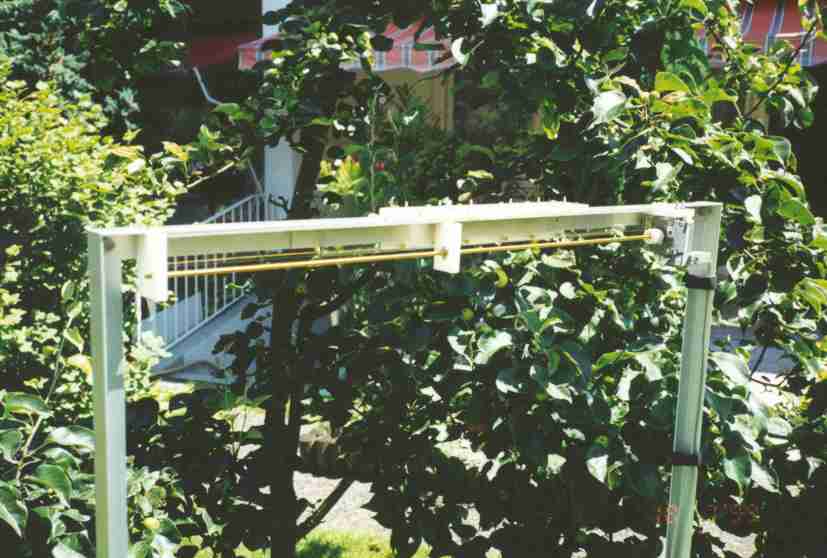 |
1999 Close-up view of integrated novel low-loss precision tuning capacitor. |
 |
1999 Close-up view of integrated novel low-loss precision tuning capacitor.
|
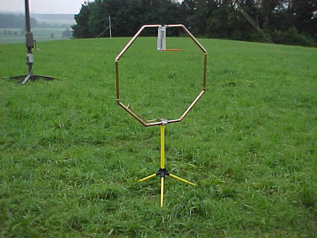 |
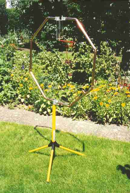
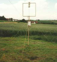
1999 Field-day of ILLER VALLEY local amateur radio association, district DOK T16 of the DARC. Octagonal magnetic loop antenna on grassland near the town of Senden / Bavaria. Photo taken by DG9SJ with digital camera. |
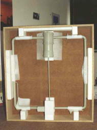 |
1994 Overseas packing for the series type QAM-Loop. Box cover removed. |
a
|
WARNING: A magnetic loop is a high-Q circuit that develops very high voltages in excess of several 1000 volts. It is very dangerous to touch the loop conductor during transmissions. RF burns heal very badly! Keep away very close from the loop during transmissions and avoid children or pets staying close to the antenna installation! When operating a magnetic loop indoors don't let your canary or parrot rest on the conductor of the loop during transmissions! Your pets will not be amused. |
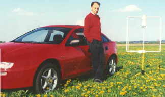 |
1995 QAM-Loop, transportable operation |
 |
Please be so kind as not to send me any enquiries regarding the supply of QAM-Loops. I no longer manufacture this antenna and I do not discuss my clients.
This site is dedicated to the sole purpose of furthering the abilities and interest of Amateur Radio. It is not an advertising site for the QAM-Loop.
Your comments, however, are nevertheless appreciated.
![]()