Compact VLF / LF air-core loop antennaby Wolfgang Buescher, DL4YHF last updated: August 2009. |
To hunt for "utility" signals on VLF and LF, a compact and portable loop antenna was built; this (still very incomplete) article shows the prototype of an active VLF loop antenna. A comparison with an older ferrite-rod antanna can be found here.
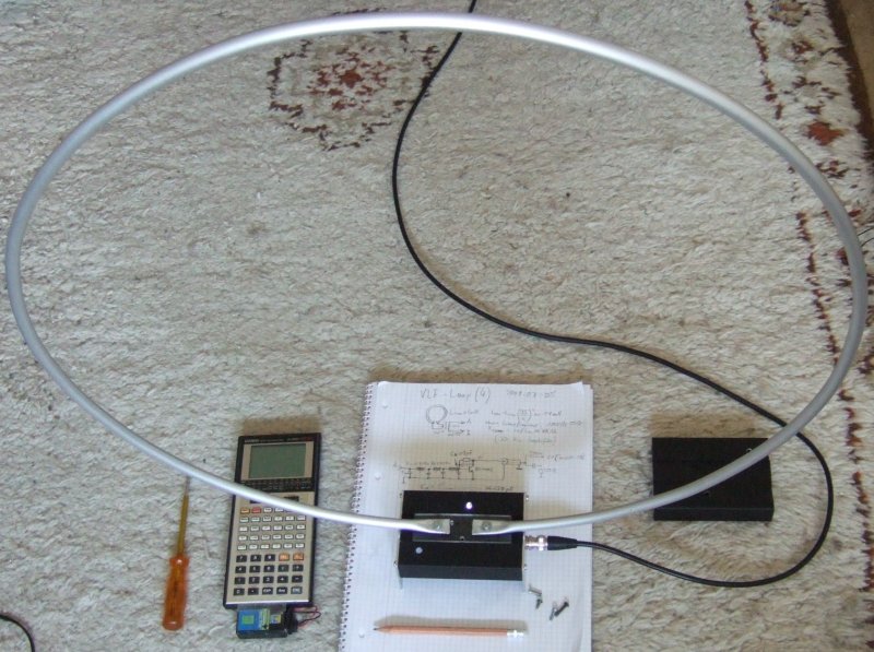
The first prototype was built from a 2 meter long aluminium tube, 10 mm diameter, which can be easily found in many hardware stores. A stiff plastic bin was used as "coil former" to bend the tube. The ends of the tube were then hammered flat to simplify mounting the antenna, and connecting it to the amplifier.
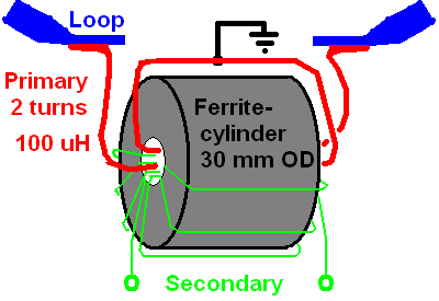
The loop diameter is about 60 cm (more would certainly improve it); the loop inductance was about 5 uH (microhenry), and the DC resistance was about 2.75 mOhm (milliohm). The voltage induced in such a loop at VLF / LF is incredibly low, so a step-up transformer is necessary between the loop and the amplifier. A large ferrite cylinder with an 8-mm bore, and an AL value of about 30 uH / sqrt(N) from an unknown source was used to build a transformer:
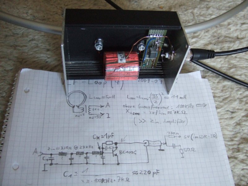
The transformer is mounted in a metal housing, which electrically shields the amplifier (and the transformer windings):
To achieve a broad frequency response, and lower corner frequency in the 1-kHz range, the amplifier's input impedance (as seen by the loop) must be equal to, or less than the loop's impedance at the lower corner frequency. Since the transformer uses two primary turns (from thick enamelled copper wire to keep the primary's DC resistance way below the loop's DC resistance), and 95 secondary turns (don't ask why I didn't use 100 turns..), the stepped-up loop inductance is roughly
L_sec = L_loop * (N_secondary/N_primary) ^ 2 = 5 uH * (95/2) ^ 2 = 11 mH .
At the targeted corner frequency of 1 kHz, L_sec gives an impedance of
Z_sec = 2 * pi * f * L_sec = 2 * pi * 1 kHz * 11 mH = circa 70 Ohms .
So theoretically, the amplifier's input resistance should be in the 100-Ohm region. A simple, but low-noise bipolar amplifier stage running at a relatively high collector current, and some negative feedback was selected for an initial test . An old sketch of the amplifier stage can be seen in the photo above; but the feedback circuit was modified later to achieve more gain in LF frequency range above 50 kHz.bl
A few LF- and VLF spectrograms, using this active loop antenna and an SDR-IQ (software defined radio), can be found here.
To eliminate an extra power supply for this loop, it uses the phantom supply sketched below. It delivers a low DC voltage to the active antenna, effectively low-pass filtered, with a current limiter (approx. 50 mA maximum). The 5 volt input is tapped inside the SDR-IQ near the USB socket. R1 and C1 are the first lowpass stage to remove "digital" noise from the 5 V input. Q1 provides a lowpass-filtered (but not voltage-stabilized) voltage of approx. 4.3 Volts at the emitter. It requires a small cooling fin (if the output may be shortened to ground). Q2 acts as current limiter, and Q3 provides a high output impedance for AC signals (like an inductor). L1 decouples the phantom supply from the coax connector for RF signals.
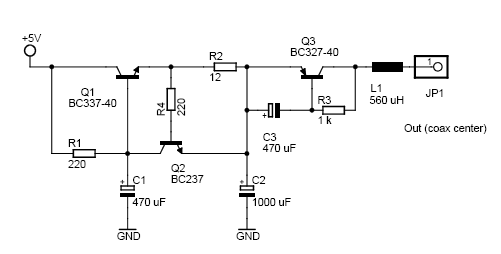
Phantom Feed Circuit (mounted inside the SDR-IQ)
Note that this simple phantom power suppy for the active antenna works properly because the SDR has an input impedance of 50 Ohms. For other 'receivers' with a larger input impedance (like the soundcard), the voltage across the 'gyrator' Q3 may cause distortion, making a more sophisticated circuit necessary (or a battery).
.. was difficult to measure indoors, since all "test signals" are incredibly strong (at least here, in Europe, with a crowded LF AM broadcast band). At least, the LF spectrum / spectrogram display showed no signs of intermodulation. Note the enormous bandwidth occupied by Loran ;-(

The initial design (with a single BC109 transistor in the preamp) leaves room for improvement. The amplifier's noise figure could be improved by a few transistors in parallel, which would also reduce the amplifier's input impedance, which in turn would reduce the lower cutoff frequency.
At least, a short test with the antenna used indoors (!), and some of the AC mains hum removed with an automatic notch filter, sferics and tweeks are nicely audible, and visible in the spectrogram (here: a reassigned spectrogram display to improve resolution along the time scale without sacrifycing the frequency resolution).
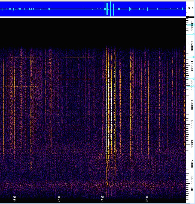
Time/frequency reassigned VLF spectrogram with RSDN (horizontal lines) and
sferics (vertical lines).
Received with the air-core loop antenna indoors, and an SDR-IQ
(software-defined radio).
back to DL4YHF's main ham radio homepage