VLF loop antennas for Radio Direction Findingby Wolfgang Buescher, DL4YHF last updated: August 2003. |
| With two crossed loops, one North/South, one East/West,
radio-direction finding on VLF is possible. If one can live with a 180°
ambiguity for the bearing (azimuth angle), a simple and small antenna like
the one presented below can be used. With the right software, the direction
of many transmitters can be displayed simultaneously on a special kind of
spectrogram.
Update 2009-07: Comparison with a ferrite-less loop showed that either the ferrite material is not optimum, or this loop requires a better shielding to defeat picking up E-field signals. Details here.
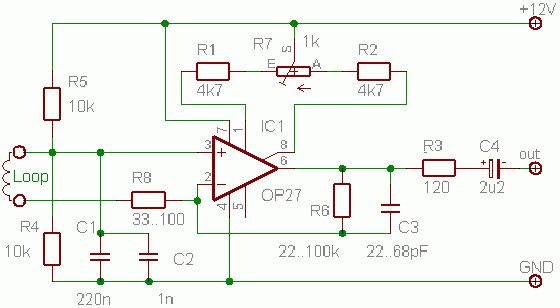
Photograph of the antenna (prototype) and amplifier schematicsHere is a photograph of the first prototype for a VLF radio direction finding antenna. Some notes on the construction of this antenna will follow later.
Both N/S and E/W loop have 270 turns on a bundle of seven ferrite rods (type unknown). The resulting inductivity is near 20 mH. At the base of the plastic tube which holds the coils, there are two identic preamplifiers, with these schematics :
R8 is used to reduce the gain below 300 Hz, and to make offset adjustment easier. The offset trimmer is a 10-turn precision potentiometer. The operational amplifier may be an OP(A)27 or an LT1007, or similar pin-compatible types. For more gain above 15kHz, other amplifier types may be better (not tested yet). The overall gain is set by R6. The amplifier's input impedance (between the op's inverting and non-inverting input) is almost zero ohms due to the negative feedback. The low input impedance is essential to compensate the loop's frequency dependent efficiency which rises at higher frequencies. C3 can be used to reduce the sensitivity at higher frequencies. If you are far away from the VLF broadcasters (submarine transmitters), you certainly don't need it. If you live near an LF- or MF transmitter, connect a capacitor with 100...1000pF parallel to the loop, to form an extra lowpass together with the loop's inductance.
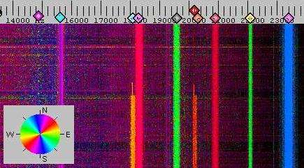
SoftwareFor radio direction finding on LF, the antenna was connected to the PC's soundcard: N/S antenna to the left input, E/W antenna to the right input. There is a 180° ambiguity with this principle. The data were processed in real time with the software Spectrum Lab, which can display a colour-coded azimuth spectrogram like this:
More recent RDF spectrograms of the VLF spectrum can be found here. With some additional hardware (including an E-field antenna), it is possible to solve the 180° azimuth ambiguity as suggested by Markus Vester, DF6NM. Markus has written a nice DOS-program with some extra features which do not exist in Spectrum Lab (yet?).
Construction NotesIf you consider to build a ferrite antenna for RDF'ing on VLF, here are some things to care about:
The ferrite material usable for LF and VLF is a relatively good conductor.
To avoid losses due to eddy currents, the ferrite rods are often slotted.
This type of ferrite rods can often be found in old longwave / medium wave
radios. The coils are not wound directly wound over the ferrites, but on a slotted aluminum tube (I made two such tubes from sheet metal, about 1mm strength, rolled over a broomstick). The slot is important, otherwise the tube would be a single-turn shortened layer around the ferrite rod. Because the ferrite is a semiconductor, it catches electric fields which would be capacitively coupled into the coil. To avoid this, I connected the aluminum tube to the preamplifier's GROUND so the tube also acts as an "inner" electric screen. To have another "outer" screen over the coil was not necessary. There was only a weak noise increase when touching the coil with the hand. Because the coils are relatively short compared to the ferrite rods (coil length = 4.5 cm, rod length = 20 cm), the coils are completely hidden inside the plastic tube which supports everything (see photo). I used several layers of HF litz wire (30 strands with 0.05mm diameter), but this is most likely overkill on these low frequencies. Single-strand 0.5...0.7 mm diameter enameled copper wire should work almost as well.
Antenna AlignmentTo find the right orientation for the loop, I calculated the bearing to the strongest VLF broadcaster (DHO38 in northwest Germany), using the coordinates from an LF station list in the RDF project by Manfred Kerckhoff. On his page you can also find an online bearing calculator (thanks Manfred & contributors ! ). Check some other receiveable stations also, to make sure you didn't connect one of the loops with the wrong polarity. Use a relatively large FFT size and slow scrolling speed, because this makes the azimuth readings less imune to noise. Of course this does not help for pulse-type signals like the Russian "Alpha" (navigation system).
Antenna CalibrationSorry... not possible yet because Spectrum Lab does not have a "loadable" calibration table. The plan is to implement a lookup table for a number of reference frequencies, which contains amplitude correction factors and phase correction offsets to compensate different phase- and frequency responses in the antenna (loops + amplifiers).
Wrong or strange bearingsThere are certain signals from nearby sources which are impossible to locate with this type of radio direction finding. If a signal does not arrive as an electromagnetic wave (but as a "loosely coupled magnetic field"), the indicated bearing depends on the orientation of the transmitting coil. If, for example, you connect an AF generator to a fiew turns of wire around a single ferrite rod, located some meters away from the RDF antenna, the colour of the azimuth display changes as you swivel the "transmitting" rod on your workbench. For the same reason, radio direction finding on your neighbour's TV flyback transformer usually fails : You don't receive an electromagnetic wave but just a stray field from the transformer. Another source of "strange" bearings are electric AC motors . The azimuth display may look like a chain of coloured pearls, caused by the slow slip between the mains frequency and the rotator's magnetic field (in an asynchronous motor; synchronous motors are not very common these days).
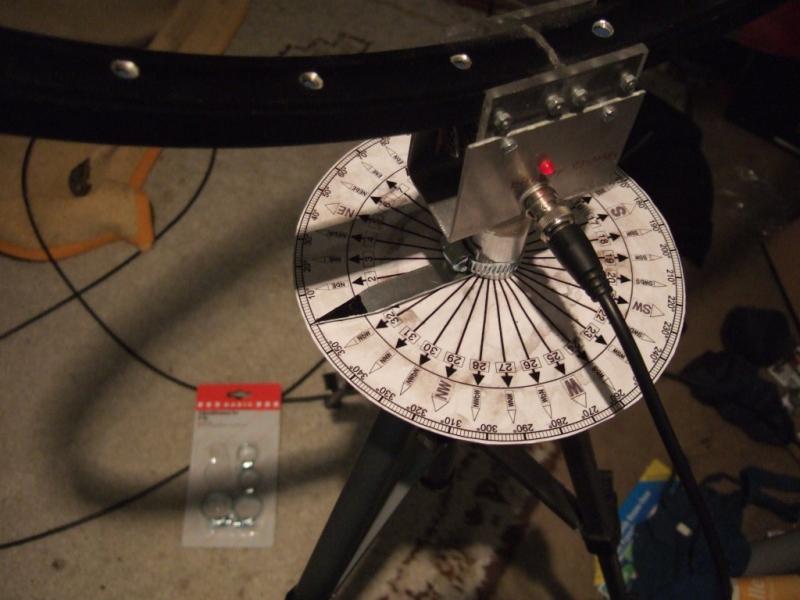
AlternativesFor 'quick' radio direction finding (without the need for a noisy computer), the 'bikeloop' antenna, mounted on a camera tripod, with a simple compass card, and a simple VLF downconverter (using an NE612 'Gilbert cell' mixer) proved to be a good alternative to find the direction towards a single transmitter. Note that unlike Claudio's bikeloop article, this is just a single loop which has to be rotated manually. In most cases, the nulls of this loop are deep enough for RDFing. The narrow cut in the aluminium rim is at the bottom (visible between the acrylic glass plates which hold the loop).
|
See also: Remote VLF E-field receiver , a collection of VLF spectrograms (mostly H-field) , back to DL4YHF's main ham radio homepage
|