DL4YHF's Amateur Radio Archive:
|
QRP Indoor Loop
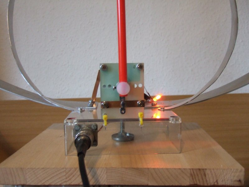
For QRP operation with limited space, a compact and lightweight 'magnetic' loop antenna
was built. For the first design (which leaves room for improvement), a long thin piece
of aluminium sheet was used (3.14 meters total circumfence, 50 mm wide, 2 mm thickness):
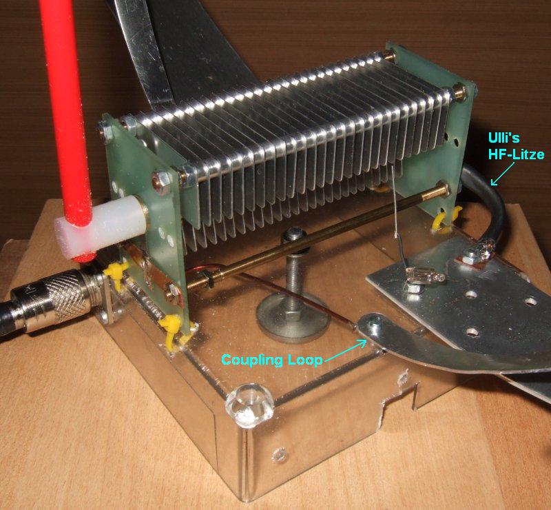
Ideas / possible improvementsThe electric conductance of the aluminium loop (measured at DC by passing 2 amperes through the loop, and measuring the voltage - 3 mV - across the loop close to its ends) was found larger than it should have been. Calculation:
       sigma = ( Current * Length ) / ( Voltage * Conducting_Area )
   here:
       sigma = ( 2 A  *  3 m ) / ( 0.003 V * 0.002 m * 0.05 m ) = 20 * 10^6 Siemens / meter

     (In Germany, 'sigma' [σ] denotes the electrical conductance.
      In the English literature, 'kappa' [κ] seems more common.)
The electrical conductivity of pure aluminium would be 36.6 Mega-Siemens per meter;
and a loop made of pure copper would be even better (sigma = 58 Mega-Siemens per meter).Since most of the HF current only flows in the outer few micrometers of the conductor, the loop doesn't have to be "solid". A loop made of a long (bent) piece of plastic, carrying a long strip of copper foil (say 70 micrometers thick, and 50 mm wide) would be even lighter than this loop. Experimentation will tell if the reduced loss in the loop is worth the effort, considering the loss in the capacitor. A thin copper loop in combination with a 'butterfly' capacitor, or -even better- a variable vacuum capacitor will help to cut the losses in the loop even further. But at some point losses in the vincinity of the loop (walls, floors, ceilings, eddy currents in metal objects, etc) will dominate, and it possibly doesn't pay off to reduce the losses in the antenna itself.
|
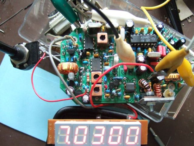
Miss MosquitaMiss Mosquita was the first QRP transceiver which I didn't design myself. But this little cutie by DL-QRP-AG caught my eye at a hamfest, so I bought the kit (for a very fair price) and assembled it in some hours on one weekend. The construction is very simple, and if you follow the detailed step-by-step instructions there should be no problem to get it running - my Miss Mosquita worked properly right from the start. Only for personal taste, I made two minor modifications which are described below. But first of all, this is how the transceiver looked (with the prototype of the first 'DL4YHF-' LED frequency counter attached) during the first QSOs - no enclosure yet, because I wanted to get "on air" with it as fast as possible :
The seven-segment frequency display is my first prototype (details about the counter are here; the counter which can be ordered as a kit from QRP-project is basically the same with a slightly modified layout). The counter (-prototype) fits easily inside the transceiver's housing (which is available from DL-QRP AG), there was even enough space under it to mount the jacks for headphone and morse key on the front panel under the display:
The boards are mounted on a copper-clad board which was inserted in a slot of the aluminum housing (like a "motherboard" holding the transceiver- and the TRX board in place). Three screws soldered (!) to the "motherboard" are used as bolts which hold the Mosquita PCB in place. I didn't remove the black adhesive stuff from the ex-photographic PC board material. The top view shows the Mosquita board with PA transistor mounted on the rear panel, and the counter mounted at the front side:
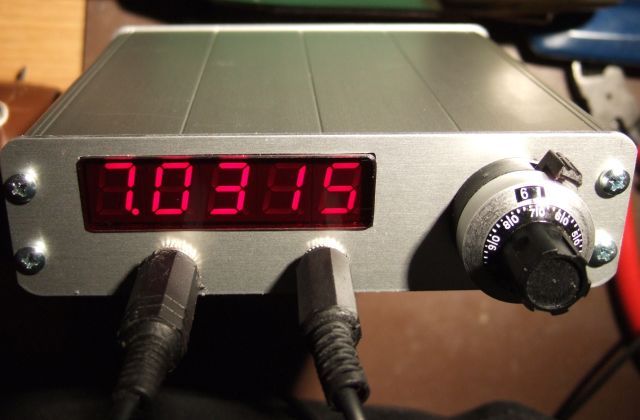
The final result looks like this, with red plexiglass in front of the 7-segment display to increase the display contrast in a bright environment (the photograph was taken in the light of a strong halogen lamp):
Mosquita modificationsAgain, Miss Mosquita worked right from the start. I made the following modification just for personal taste: The CW pitch was a bit low (audio center frequency about 400 Hz). Since I prefer 650 Hz for CW, I modified the BFO, TX-mixer a bit, and reduced the audio bandwidth to something about 400 Hz:
The VFO can be easily tapped for the (LED-) frequency counter between R15 (820 Ohm) and P3 ( 250 Ohm to ground). Digital frequency readout for Miss Mosquita (DL4YHF counter)I found the oscillator in the TX mixer running at 3.9990 MHz, so I added this frequency in the table of "preconfigured" offset frequencies in the PIC16F628 firmware (use "counter2.hex", also for the counter kit from QRP project). If your counter is preprogrammed with an IF offset of ZERO, here are the steps how to get it running properly with Miss Mosquita's 3999 kHz TX-mixer:
If everything went right, the counter shows something like "7.0300" (MHz) now. Bingo.. connect an antenna and listen for QRP stations, or start calling CQ on that frequency ;-)
Additionally, you can activate the power-saving option in the counter's setup menu (toggle "PSAVE" and "NoPSV" in programming mode). If the power-saving option is enabled, the display will be turned off if the VFO frequency doesn't change by more than a few dozen Hertz within 15 seconds, and turned on as soon as the VFO frequency changes again (=operator turning the VFO knob). During power-saving mode, the display flashes up once every 10 second to show that the transceiver is still on. This mode can save up to 15 mA of battery current. In the author's prototype, the average total DC current during RX for receiver+counter dropped from 45 mA to 32 mA with the power-saving mode.
|