Phasing LF Exciter for digital modes on 136 kHz
by Wolfgang "Wolf" Büscher, DL4YHF
last modified in January 2005. |
Main Site:
www.qsl.net/dl4yhf
Backup site at
freenet.de
|
Up to now, this project is in the "early breadboard state", but initial tests
with an ugly dead-bug style construction showed a surprisingly good suppression
of the carrier (138.55 kHz) and the unwanted sideband. Using I2PHD's JASON
or DL4YHF's Spectrum Lab to produce audio signals with quadrature output
(I+Q), the "wanted" signal was S9 + 20dB on my TS850 while the carrier and
the "unwanted" sidebands produced no S-meter reading in all cases (only weakly
audible!).
 Two outputs
signals from the soundcard ("left" and "right" channel) provide an audio
signal with a 90° phase difference between them. By convention, the
"right" output lags the "left" output by 90°. When building the prototype,
I didn't care much about where to connect "I" and "Q" to the IC pins... if
the mixer produces USB instead of LSB, or LSB instead of USB, simply reverse
the two audio inputs. The same is true if you swap the inverted and non-inverted
buffered audio signal in one of the two mixer branches.
Two outputs
signals from the soundcard ("left" and "right" channel) provide an audio
signal with a 90° phase difference between them. By convention, the
"right" output lags the "left" output by 90°. When building the prototype,
I didn't care much about where to connect "I" and "Q" to the IC pins... if
the mixer produces USB instead of LSB, or LSB instead of USB, simply reverse
the two audio inputs. The same is true if you swap the inverted and non-inverted
buffered audio signal in one of the two mixer branches.
The audio buffer uses a TL084 quad audio OPAMP to produce four audio
signals:
-
AI+ = "Audio, in-phase, positive polarity"
-
AI- = "Audio, in-phase, negative polarity"
-
AQ+ = "Audio, quadrature phase, positive polarity"
-
AQ- = "Audio, quadrature phase, negative polarity".
The four buffered audio signals are fed into two single balanced mixers,
realized with a 74HC4066 (four analog switches). Both mixers are fed with
the same L.O. frequency (138.55 kHz in my case), with a 90° phase difference
between both L.O. outputs.
The L.O. is shown in the next chapter, it actually produces 4 outputs, quite
similar to the audio signals: In-phase, quadrature-phase, and for both of
these inverted and non-inverted outputs.
The outputs from both mixers are simply added via the two 1-kOhm-resistors,
which are also part for the first lowpass filter. The combined output only
contains the "wanted" signal, and some higher harmonics, which can all be
filtered out with simple lowpass filters.
Local oscillator with quadrature outputs
There are many ways to build a local oscillator with quadrature output, including
DDS, programmable devices like microcontrollers, etc. But since the 136 kHz
amateur radio band is so narrow, it easily fits into the bandwidth of a soundcard
(even if the soundcard only runs at 11.025 kHz). So, instead of changing
the L.O. frequency, we change the audio frequency to "QSY". The L.O. only
needs a fixed frequency which should be a few hundred Hz away from the upper
of lower edge of the 136 kHz band.
 Fortunately
this can be easily achived with standard components, and a standard crystal
frequency: 4.433619 MHz. The crystal frequency is divided by 8 using a simple
counter (a 74HC161 is only one of many possibilities). The oscillator itself
may be placed in a small "oven" if ultimate frequency stability is
required.
Fortunately
this can be easily achived with standard components, and a standard crystal
frequency: 4.433619 MHz. The crystal frequency is divided by 8 using a simple
counter (a 74HC161 is only one of many possibilities). The oscillator itself
may be placed in a small "oven" if ultimate frequency stability is
required.
The result is a signal near 554.202 kHz. This drives another divider (using
the two J/K-master/slave flipflops in a 74HC107). This final divider produces
four (!) output signals near 138.5506 kHz:
-
I+ = In-phase output from L.O., non-inverted
-
I- = In-phase output from L.O., inverted
-
Q+ = Quadrature output from L.O., non-inverted
-
Q- = Quadrature output from L.O., inverted
The inverted L.O. outputs are only required if a (74HC)4066 is used as the
mixer. Other analog switches, usually "analog multiplexers", may not require
complementary switching signals (but only "I" and "Q" from the L.O.
instead).
To use this circuit in a "high-power" transmitter, good shielding of the
mixer, and some lowpass-filtering of the audio signals may be helpful. Any
transmitted RF which enters the analog mixer ports may degrade the unwanted
sideband cancellation.
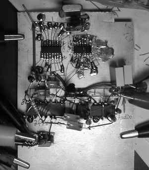
More construction details, and possibly a nicer photograph of the first prototype
may appear here in future, after some cosmetic surgery...
The two IC's at the top are the 74HC161 and -HC107, in SMT, soldered on a
copper-clad board. A sharp knife was used to cut the "layout" into the
copper.
The two IC's at the bottom are the 74HC4066 and the TL084, both "dead-bug
style" (with the legs in the air, the resistors and capacitors soldered directly
to them). The audio I+Q signals are connected at the right side. The "RF"
output (136.x kHz) is in the lower left corner.
Further reading
A much nicer drawing of a similar image-cancelling mixer for the LF bands
was made by John Andrews, so if you are interested in the subject don't miss
this one:
http://www.w1tag.com/Phasing.htm