About a project that began many years ago, and still is not finished.
Some time in the late 80's, some of our local group heard about of a project of an amateur radio group in Munich who designed and built a mobile Doppler-direction finder. This is a device that can detect the direction of a RF signal without the necessity of moving antenna parts. The group offered a kit consisting of the schematics, the PCBs, and the antenna unit for 2m (see below). Joerg (DL1SEL) and later also Jochen (DL4SCI) ordered such a kit, and so two of these devices were built.
Soon after the first direction finder was finished (I think it was some after 2:00am), there was the idea of an automatic direction measurement unit. It should be controllable by packet radio, and with a second of such a station, a location finder would be possible.
To make it even more comfortable, the direction finder stations should be controlled from one point that also collects the direction data and presents the results to the user. But until we got so far, it was a long, long way, and we have not yet reached our goal.
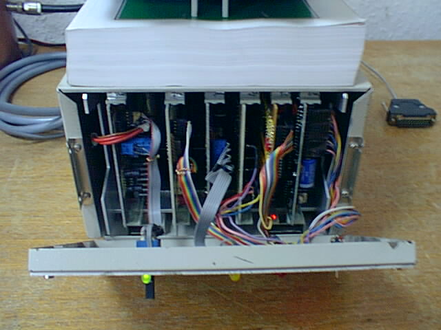
Below you see the complete direction finder system at DB0ADF,
which consists of several Euro-size PCBs (160x100mm)
mounted into an old modem-housing. It also contains the
controlling processor board and a TNC for packet radio.
Normally, when the direction of a RF signal shall be measured, one takes an antenna with a non-isotropic direction diagram (e.g. a dipole, a HB9CV or a yagi) and searches for the maximum signal strength on the receiver while turning the antenna (Often it is better to use the minimum as well for the fine detection of the direction).
The Doppler-principle is somewhat different from this. It does not use the field strength at all (despite the signal may not be too weak to detect it anyway), but relies on frequency or phase changes of the received signal. That's the reason why a normal FM receiver - it does not even need an S-Meter - is sufficient for the task.
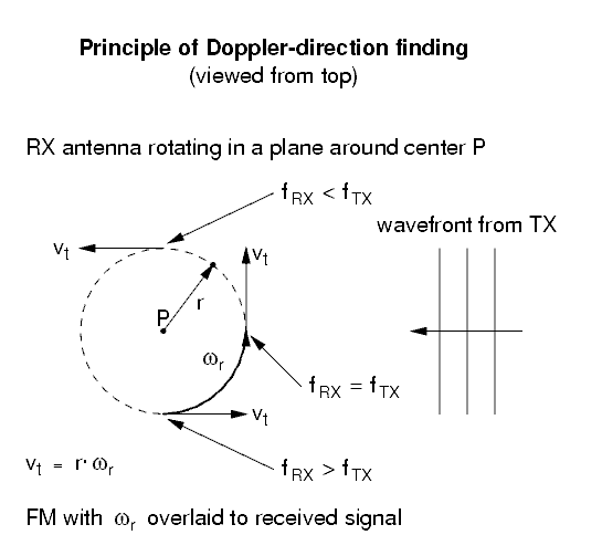
When talking about the Doppler-principle, you know that when approaching a source of sound or electromagnetic radiation, the frequency you receive gets pitched upwards. When moving away from the source, the frequency you receive gets lowered. So it is possible by moving around in the x-y-plane (just imagine the earth is flat to make things easier in this case :-), and watching the change in frequency, to find out where the signal is coming from.
The following diagram illustrates the basic principle of
a Doppler-direction finder:
But what we want is a solid state system without moving parts. This is achieved by replacing the one rotating antenna by several antennas which are fixed on the border of a circle. The receiver is fed from a switch that circularly selects all antennas around the circle, thus simulating the rotation. But because there is no movement, it is not really the Doppler-shift that is used. It is rather the different phase of the RF signal at different locations that is measured.
The next diagram shows how that works:
There are e.g. 4 antennas arranged in a square with a distance
of 1/4 wavelength to the neighbor. A fader, incorporatig a
set of PIN-diodes and controlled by some kind of multi-phase
oscillator, fades over between the signals of the 4
antennas and feeds this signal to the FM receiver.
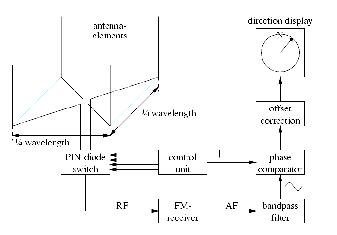
Fading instead of hard switching is done to avoid phase discontinuities in the RX signal. This way the receiver sees a signal whose phase is interpolated between the phases at the antennas' locations. A sudden phase change would result in a infinite high frequency change for a infinite short time, and thus cannot be properly followed by a receiver with limited bandwidth.
The AF-signal of the RX is fed through a narrow bandpass that lets only pass the rotation frequency of the switch (Filter and antenna switch are clocked by a central source). This is necessary for two reasons: To remove harmonic distortions from the received rotation signal, and to avoid interference from modulation on the RX signal, which normally will not be a plain carrier but carry e.g. voice or packet radio signals. The phase between the filtered signal and the switch rotating signal is measured by a digital counter circuit and displayed. This phase angle directly corresponds to the direction of the received signal.
Although the approximation of a circle by a square is very rough, at least in theory the direction is exactly reproducable.
The antennas should not be much more than a quarter wavelength separated from each other, because the fading else introduces too severe AM modulation (imagine fading from one signal to another one that is delayed by a half wavelength, which means fading from some signal to its inverted one: This would introduce a point where the resulting signal disappears and makes a phase-jump by 180 degrees). If the antennas are too narrow to each other, the phase difference will become too low and thus the deviation of the resulting FM will diappear in noise. This means that for every amateur radio band, a separate antenna unit will be necessary for the direction finder.
According to Shannon's theoreme of sampled signals, at least three antennas (== sample points per rotation) are needed to obtain an FM signal from which the phase in correspondence to the rotation can be reconstructed (which seems logical in that the receiving array should span some area and not consist of only a line with 2 points).
The rotation frequency proportionally influences the resulting FM deviation at the receiver. It is best chosen to be below the used audio frequency band, at about 200 to 300Hz. This also reduces the sensitivity to voice modulation. The use of a very high rotation frequency is discouraged, because the kind of modulation performed by the switched antenna array can fold signals of ajacent channels into the receiver channel, thus reducing the selectivity.
Because of the group delay of the entire FM-receiver path a calibration between the antenna switch control and the phase detector is required. This is easily done by adding a fixed phase angle to the result. This offset has to be calibrated once and will also correct for a angular misalignment of the antenna construction.
A more severe source of errors is multi-path reception. This means that we don't have the ideal case of a straight wave front reaching our antenna-field, but there are additional wavefronts from other directions as a result of reflection by buildings, hills or mountains, or other antennas in the direct neighbourhood.
These errors are very difficult to estimate and can lead to a totally wrong direction indicated by the direction finder. The simple linear addition of two waves does not result in a simple superposition of two sinewaves at the FM discriminator output, not even with a real rotating antenna. Arrangements with more antennas have an advantage in these cases. By passband-filtering of not only the rotation frequency in the audio signal, but also its harmonics, and by the use of suited signal processing techniques, errors can be detected and in some cases a correction to some degree is also possible.
That means that good results with a doppler direction finder will only be obtained if the receiving antenna is in a free environment e.g. above the roofs in a city, or on a hill without surrounding buildings or woods, and the signal is also free of reflections in the far range.
This page was last modified 2000/04/22 by
DL4SDC.
It can be viewed with any browser.