|
|
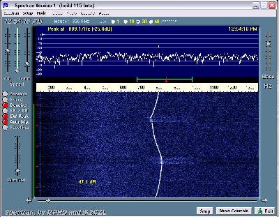
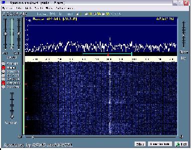
I had known for many years that the IC706 had a temperature related frequency stability problem in CW and SSB. This is not a major problem - the drift cycles by about +/- 30Hz over a 2 minute period as the fan is switched in Rx mode, as you can see from the 'before' plot above. In normal usage this drift is only just enough for the ear to detect - if you know what you are listening for - and would not be an issue for CW/SSB QSO's. I found this when using FFTDSP to monitor GB3MHS when I was building it in 1998.
The two comparison pictures above were captured using Spectran while monitoring the DB0AAT beacon on 23cm.
Once identified and understood,I didn't really worry about it - however, with an increasing interest in JT44/65, I decided to do something about it!
An internet search lead me to IC 706 mods , where I found the problem described and a solution given for the 706MkIIG. Instead of having the fan switched, it is run at low level permanently while on Rx - this is enough air-flow to prevent the need for it to be switched on at normal temparatures. A 220R resistor bleeds enough current to run the fan - I used a 5W type because it was available - I would not recommend going below 1W, although calculation says a 0.6W should handle the power
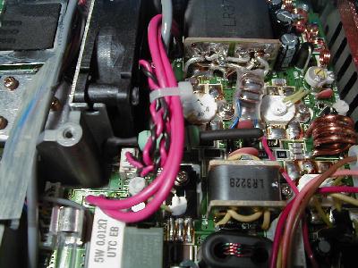
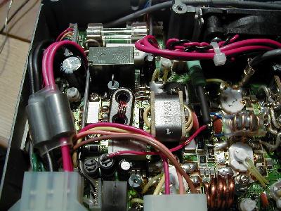
However, on opening the bottom cover of the rig, I discovered that the MkII has a different location of components on the PA board as compared to the MKIIG, so the pictures referenced were not a lot of help! For the MkII the correct point to pick off the +12v switched is shown in the picture below - the same circuit point as for the MkIIG, but a different physical location on the board.
One end of the resistor is connected to the +12v switched line, picked up from the top of the ferrite choke. The other end is attached to the + line to the fan - a small white two pin connector is visible in the left hand picture below - just to the side of the fan. Carefully form and solder the resistor lead to the tab corresponding to the + (red!) connection of the socket. There is not much space to bring the lead up from the connection point, so I would recommend insulating it to avoid any risk of shorting the +12v to the chassis due to vibration etc. Be careful about where you position the body of the resistor, so that any heat generated does not cause the insulation on other cables to be damaged.
 |
 |
page created 08.02.04 page last updated: 08.02.04