Agilent E5062E, 2-port network analyzer to 3GHz
yes, exactly...
Measurement Results
I have done the measurements in two sessions. At first, I have measured the reflection only to show that a very good match can be reached on each hf-band. I have used an Agilent Networkanalyzer E5062A. I prefer the representation of the the S-parameters but I think not everybody really know what they are. Therefore I also published the SWR diagramm of some frequency ranges. There is a way to calculate the SWR from the s-params, but you should at least remember that -10dB is (almost) equal to VSWR of 2. You can tune the antenna on each arbitrary frequency between 1.8MHz and 30MHz. You can always reach a SWR of at least 1.15, which really should be enough... there is absolutely no need for an additional antenna tuner. Well, it becomes very narrow on the low-bands but that just means that the Q-factor is very high (you could increase the bandwidth by inserting an resistor).
Who thinks that a good SWR is everything, may use a dummy load. Even more important is how good an antenna radiates. Therefore I have measured the radiation of the DK§ and have compared it with a Lambda/4 vertical antenna. Felle free to look at the results on the lower part of this site.
|
|
|
|
Agilent E5062E, 2-port network analyzer to 3GHz |
yes, exactly... |
...any questions? Just drop me a line via e-mail.
|
|
|
|
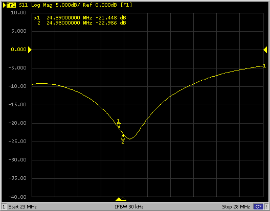
S11 in the range between 23- 28MHz, the two marker show the lowest and the highest frequencies in 12m band
|
SWR in the range between 23 - 28MHz, the two marker show the lowest and the highest frequencies in 12m-band
|
 |
 |
| S11 in the range between 10- 30MHz, the two
marker show the lowest and the highest frequencies in 15m band
|
S11 in the range between 15- 20MHz, the two
marker show the lowest and the highest frequencies in 17m band
|
 |
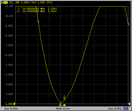 |
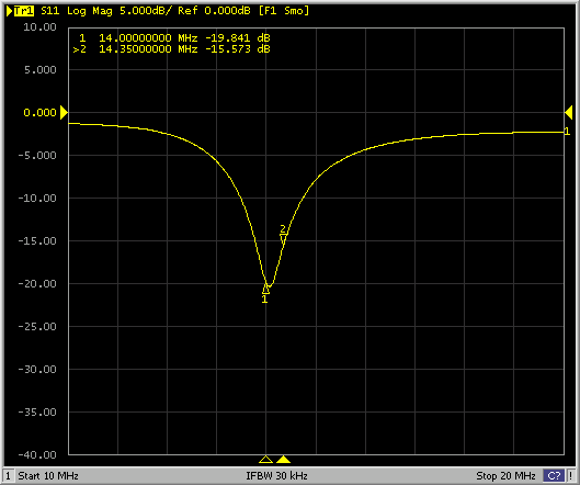
| S11 in the range between 10- 20MHz, the two
marker show the lowest and the highest frequencies in 20m band
|
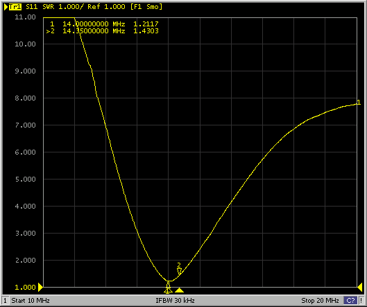
SWR in the range between 10 - 20MHz, the two
marker show the lowest and the highest frequencies in 20m-band
|
 |
 |
| S11 in the range between 5- 15MHz, the two
marker show the lowest and the highest frequencies in 30m band
|
SWR in the range between 5 - 15MHz, the two
marker show the lowest and the highest frequencies in 30m-band
|
 |
 |
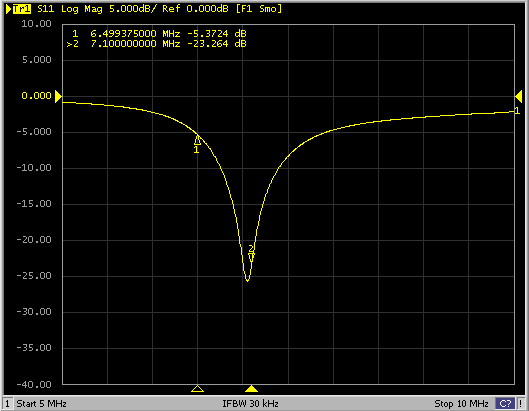
| S11 in the range between 5- 10MHz, the two
marker show the lowest and the highest frequencies in 40m band
|
SWR in the range between 5 - 10MHz, the two
marker show the lowest and the highest frequencies in 40m-band
|
 |
 |
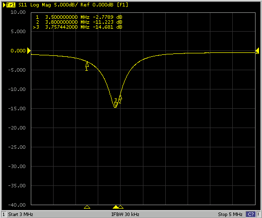
| S11 in the range between 2- 5MHz, the two
marker show the lowest and the highest frequencies in 80m band
|
SWR in the range between 2 - 5MHz, the two
marker show the lowest and the highest frequencies in 80m-band
|
 |
 |
| S11 in the range between 1.8 - 1.9MHz, the
two marker show the lowest and the highest frequencies in 160m band The 10dB bandwidth is only 1.8kHz!!!!
|
SWR in the range between 1.8 - 1.9MHz, the two marker show the lowest and the highest frequencies in 160m-band The SWR 1:2 bandwidth is only 1.8kHz!!!
|
It is kind of complex to measure the gain and the radiation pattern on low frequencies. You should be in the farfield which means to be about ten times wavelength away from the antenna that you want to measure. For example you should be about 400m away from the antenna if you want to measure in the 40m band. You also need an additional reference antenna where the gain is known if you want to measure the gain of an antenna. I have used a Lambda/4 radiator. The gain is known, it's 2.15dBi. This antenna is easy to build and has the same polarisation like the DK3 (vertical).
I have wraped some wire on a 10m long fishing-rod. Marko, a friend from work, helped me doing these measurements. Three Lambda/4 radials were used as ground. That way, a vertical for the 40m band was created very fast. But we also wanted to measure the 80m and 20m band as well. We could easily cut the wires to tune the antenna for the 20m band while we had to insert a coil for the 80m band since the fishing-rod was only 10m long.
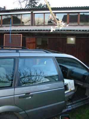
Now something about the measuring set-up. At first we have set up the reference antenna and I transmitted with 100W power. Marko measured the field strength in about 400m distance with a spectrum analyzer. The RX antennas was just a short piece of wire (about 3m). That was enough since we had enough tx power and we just wanted to get the relation of field strength between the DK3 and the reference antenna. There was no need to know the absolute field strength. However, after we have measured the power level of the reference, I transmitted using the DK3 and Marko measured the field strength again. I also drove a narrow circle while TXing so we know how much the field strength varies and to see if there is a main lobe. We didn't see really a big difference, especially on 80m and 40m since the car is very small compared to the wave length. But we saw some changes in the 20m band where the length of my car equals already Lambda/4.
|
|
|
|
Marko is measuring the strength of the field with a spectrum analyzer. The RX-Antenna is only a short piece of wire.
|
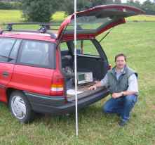
I had a networkanalyzer in my car to measure the reflection of the reference antenna. I also used my IC706MKIIG for TXing with 100W power. |
|
|
|
|
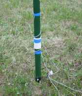
The Lambda/4 reference radiator. Here you can see the coil that was needed for the 80m band. |
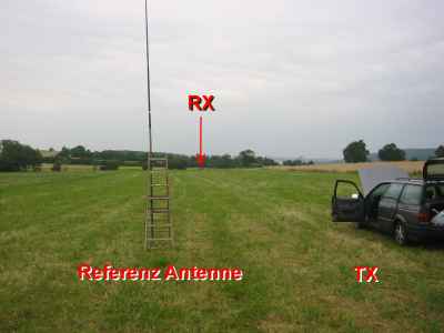
A view over the location. The distance between RX and TX was about 400m (1300ft). |
Here the measurement results:
| Frequency | reference antenna | max gain | min gain | gain (average) of the DK3 |
| 14.1 MHz | Lambda/4 | +0.8 dBd | -4.3 dBd | -0.9 dBd / 1.25 dBi |
| 7.1 MHz | Lambda/4 | -2.3 dBd | -4.5 dBd | -3.3 dBd / -1.15 dBi |
| 3.7 MHz | shortened Lambda/4 | -5.9 dBd | -7 dBd | -6.3 dBd / -4.15 dBi |
Remark: The ground works like an electrical wall (means e-field is zero). You now may conclude that this antenna has the same radiation pattern like a dipole in free space. Therefore the gain appears like if the dipole would have been the reference antenna (dBd). That does not really apply for the 80m band because I used an already shortened antenna as a reference.
|
|
|
|
S11 of reference antenna in the range between 10- 20MHz, the two marker show the lowest and the highest frequencies in 20m band
|
SWR of reference antenna in the range between 10- 20MHz, the two marker show the lowest and the highest frequencies in 20m band
|
|
|
|
|
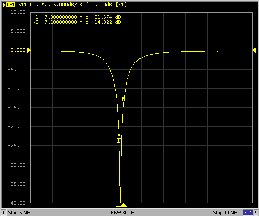
S11 of reference antenna in the range between 5- 10MHz, the marker two shows the highest frequency in 40m band.
|
SWR of reference antenna in the range between 5- 10MHz, the marker two shows the highest frequency in 40m band.
|
|
|
Unfortunately I have forgot to save the SWR in the 80m band. However, you can see a SWR of lower than 1.5 from the S11 chart. |
|
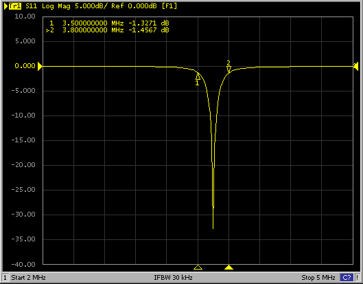
S11 of reference antenna in the range between 3- 5MHz, the two marker show the lowest and the highest frequencies in 80m band.
|