|
The 2x6-El.-Cross-Yagi (28 Ohm, 2.60 m Boom) by Henk, PA3GUO He has an excellent report about building and measuring the X-mounted Cross-Yagi, use this link: |
 |
| Cross-Yagis for EME | Cross-Yagis for
Terrestrial and Satellite Work |
EME-DXpeditions
by PA2CHR
with DK7ZB-Yagis |
|
The 2x6-El.-Cross-Yagi (28 Ohm, 2.60 m Boom) by Henk, PA3GUO He has an excellent report about building and measuring the X-mounted Cross-Yagi, use this link: |
|
![]()
 |
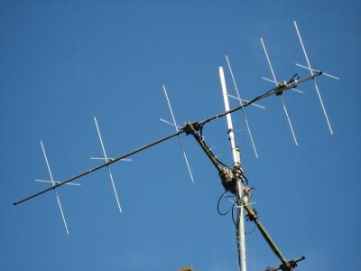
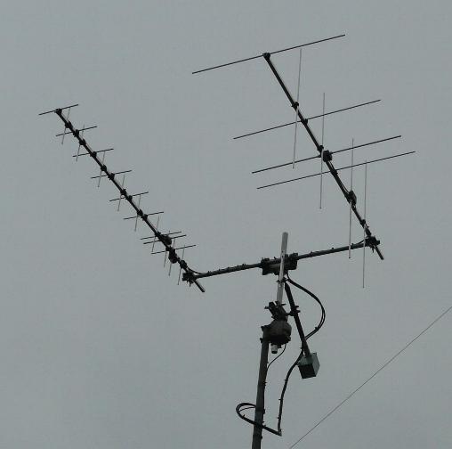
For two purposes a Cross-Yagi can be useful: Satellite work or if you need both vertical and horizontal polarization for terrestrial contacts. You can use two different feeding methods: Always cross polarization or switchable for vertical, horizontal an right hand cross polarization. The picture left shows 2x7-El-DK7ZB-28-Ohm-Yagis and a commercial 70cm-Crossyagi at the station of Bernd, DO1NBW. The mounting method in this case is the "cross". Use the 28-Ohm-Yagis, not the 12,5-Ohm-Yagis! |
|
Fig. 1 The "X"-mounting is recommended, if you will not switch between the polarisations, because it is difficult for this configuration to get horizontal and vertical polarisation. The antennas should be in the circular polarisation-mode.
|
 |
 |
Fig. 2 The "cross"-mounting is useful for two separate coax-cables for each plane and a phasing box (description below) for vertical, horizontal and circular polarisation. To get the right phase shift of 90° two mounting methods are possible: Either the two planes are mounted with a difference of lambda/4 on the boom or as close as possible and then use a coax cable which is lambda/4 longer for one plane for the 90° shift. |
|
Fig. 3 It is possible to mount the two Yagis separate with two cables and the phasing box, but this needs more space. Equal lengths of coax are needed for both planes. The support-tube must be of non-conductive material! It is counterproductive to mount the coax-cables on the support tube, because you have metallic material again in the antenna plane. Always lead the cable behind the reflector and from that point the coax should make a loop and then connect it to the center of the mast in the middle of the antenna structure. |
 |
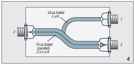 |
Fig. 4 The circuit for circular polarisation
|
|
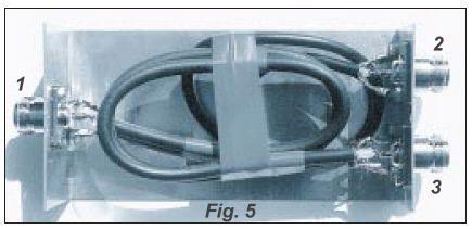
For this box you need separate coax cables from the horizontal and vertical plane with exact the same length. Four options can be realized: 1. Vertical polarisation with the cable of the vertical plane of the Yagi 2. Horizontal polarisation with the cable of the horizontal plane of the Yagi 3. Right hand circular polarisation: Horizontal plane to connector 1, vertical to connector 2, to station connector 3 3. Left hand circular polarisation: Horizontal plane to connector 2, vertical to connector 1, to station connector 3 |
|
Fig 5 The box with the phasing and matching cables. Use N-Connectors! |
|
The following pictures are the look from the reflector side of the Yagi!
 |
 |
|
Circuit for right-hand circular polarisation (RHCP) The horizontal dipole is connected to the vertical dipole with a phasing line of a quarter-wave cable of 50-Ohm-coax. At this point the impedance is 25 Ohm, which is transformed to 50 Ohm again with two parallel 75-Ohm-quarter-wave cables. The phase shift between D1/D2 and D3/D4 is +90°. It is possible to run with two cables from each plane to the station with the box for circular polarisation (Fig. 4). |
Circuit for left-hand circular polarisation (LHCP) The horizontal dipole is connected to the vertical dipole with a phasing line of a quarter-wave cable of 50-Ohm-coax. At this point the impedance is 25 Ohm, which is transformed to 50 Ohm again with two parallel 75-Ohm-quarter-wave cables. The phase shift between D1/D2 and D3/D4 is -90°. It is possible to run with two cables from each plane to the station with the box for circular polarisation (Fig. 4). |
 |
The 2x4-El.- and 2x9-El.- 28-Ohm-Cross-Yagis, both RHCP, by Piotr, SP5MG
The SWRs of the Cross-Yagis, click to enlarge! |
|
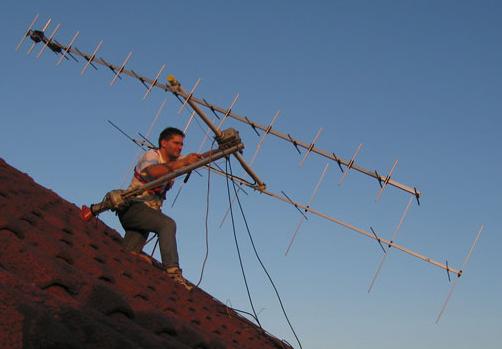
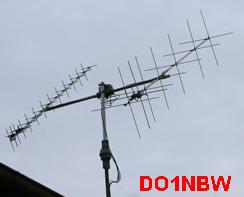
Bernd, DO1NBW mounting his Yagis |
|