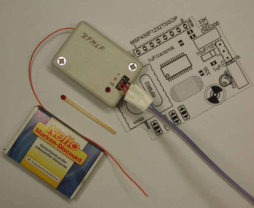
Last update : 26-November-2007

RFMLF
Power monitor and Lost and Found Transmitter
(LPD frequency range) 
This project incorporates 3 helpful units for model air plain pilots.

pic2(LPD frequency range)   (LPD frequency range) rfmlf3.jpg   
    (click to the pictures)

  •  Battery power monitor 

    A dual color LED provides information about the current battery condition. The color and the blinking frequency informs about how good  charge still is. The power monitor provides a kind of memory for the lowest voltage ever reached  since power has been turned on, even in the air. There are 5 different levels.

  • Battery power empty warning during flight

    Before the battery voltage  of the plain reaches the lowest level, an on board 433 MHz transmitter starts a low voltage warning . Any 433 LPD  hand held receiver can receive the signal.
  • Lost and Found monitoring if plain escaped

    Via a RC channel , a 433 MHz transmitter can be turned on to provide a FM signal for locating a lost plain. The transmitter emits an alternating RF signal with 4 different power levels automatically .  This allows locating of  missing plain in a wide distance range.

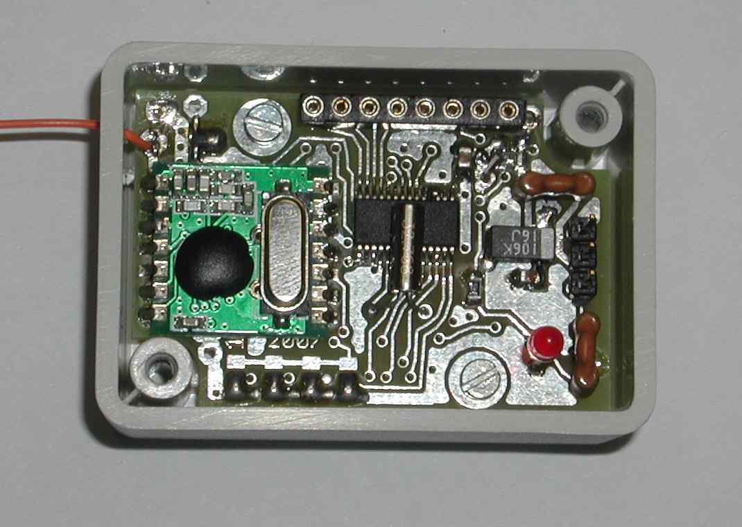
 HW: A MSP430F1232 controls a Hope RFM02 transmitter module. 


Features:
Size : 30mm x 43mm  (without box)
RF range : 4 channels      433.400    MHz    LPD CH 14
                433.800   MHz    LPD CH 30
                434.200   MHz  
 
LPD CH 46
                434.650   MHz    
LPD CH 64
Power range : 4 levels       - 13   dBm
                                         -  7   dBm
                                            1   dBm
                                            3   dBm  ( with optimal environment)
Power consumption :        Transmitter active    :      35 mA ( full power setting, LED on)
Voltage :                          3.5 .. 5.4 V external power  (via a standard RC connector)
Battery power monitor :     
       Battery                           color        blinking frequency     RF low voltage warning  
> 5.0 V                                   green                           slow                                     off
> 4.8 V                                   green                            fast                                     off
> 4.6 V                                   orange                          slow                                    off
> 4.4 V                                   orange                           fast                                    off
> 4.2 V                                      red                              slow                                    on
< 4.2 V
                                     red                              fast                                     on


Look at the schematic here. (pdf)
The assembly drawing of the PCB can be found here. (pdf)


Back home