|
|
|
|
| Spring | Summer | Autumn | Winter |
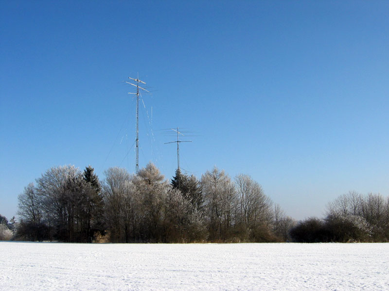
7-Element-Yagi for 10m, vertical array for 80m + 160m

4-Element-Yagi for 20m, 4-Element-Yagi for 15m, 4-Element-Yagi for 15m fixed
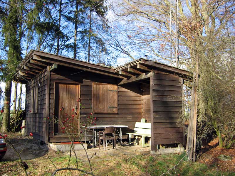
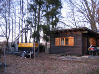
Hut
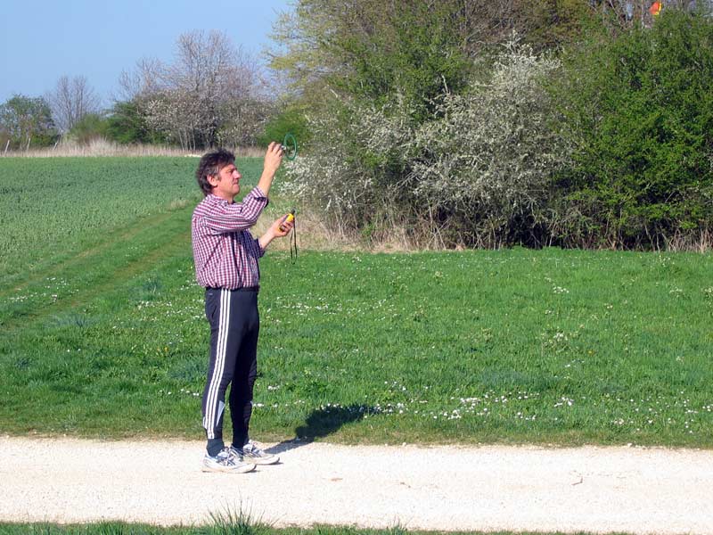
We will examine the vertical arrays closer and check the NEC4 models.
Beside the field strenghts in different directions, the impedances and hf currents on the aerials are measured.
The results are still being evaluated. Up to now, however, the precision of the measurements is surprising. We could reproduce the measurements (80m-band H field) one week later in all points up to 0.1 dB.
 |
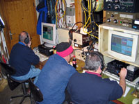
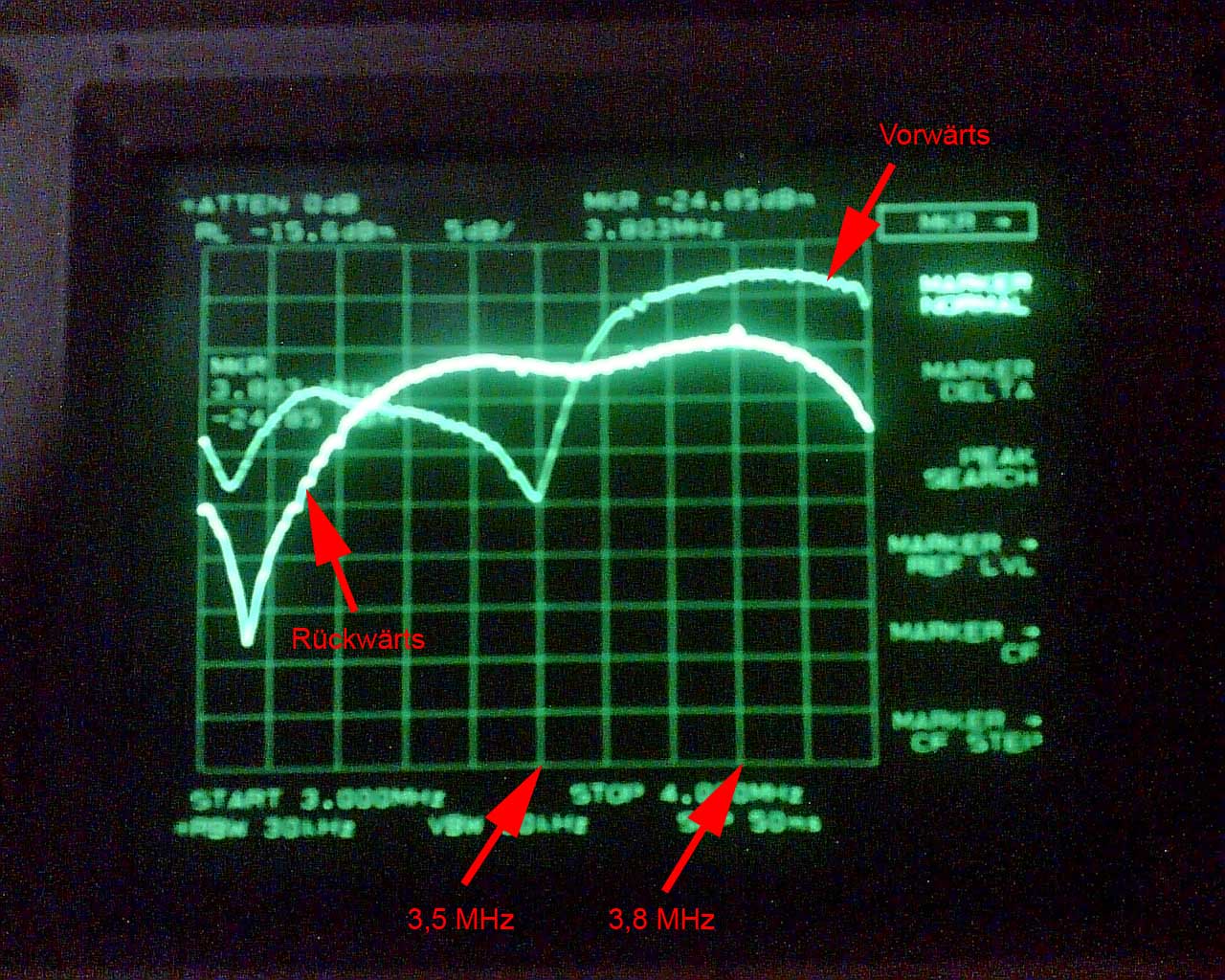 |
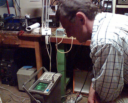
| Hannes at the measurement | Display of the spectrum analyzer |
These pictures have originated with the examination of the front to back relation of the 80m-aerial (picture 3.8 Mc SSB DX area). Besides, a reception aerial offset in ray direction was connected to the spectrum analyzer. The whole frequency response is logged twice. In the picture one can recognise the gain response and the reverse damping. Of course, only the relative field strength in measured.
As ground net we use chicken-wire which is covering the lot completely (60m x 60m). The conductivity arround every vertical feeding and grounding point (more than 30) is improved by copper discs which are interconnected by copper strips. Not only the mesh but also the 10 cm wide stripes grew into the earth. From time to time we put new chicken-wire on more or less corroded older layers.
The surrounding ground is farmland with a rather thin layer of humus soil and loam on jurassic stone. The electrical parameters change quite much with humidity, temperature etc. , all in all they are less than average. This disadvantage is overcompensated by sloping ground to eastern and southern directions. Paths to northeast and west are flat. To north and northwest we have to deal with a little elevation of about 5m with maximum in 200m distance. As we found out radiation of ground mounted verticals is not seriously degraded on 160 and 80m, but quite dramatically on 40m.
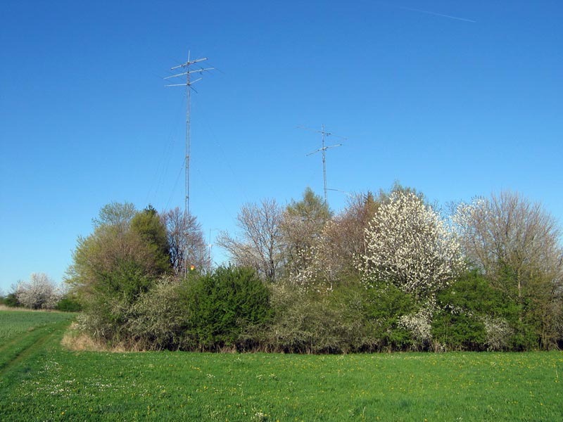
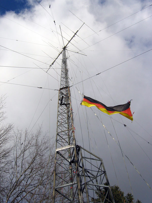
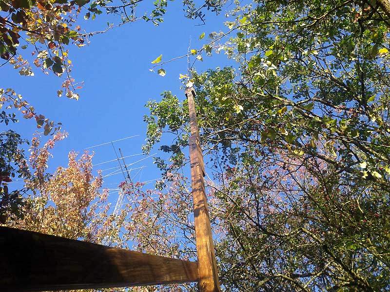
We have two taller lattice towers on the lot. One is carrying a 10m 7el Yagi at 35m and the other a 20m 4 el at 28m and a 15m 4 over 4 stack below. A small 12m tall tower right at the hut carries a 10m 4el and acts as director/reflector on 80m.
For 160m we use both bigger towers - the 35m tall as part of an array, the 28m tall as monopole, when the other is used for 80m at the same time in contests.
For feeding the tall tower which is luckily electrically much longer than Lamda/4, we just use a sloping line, which is fixed at 15 m. We would never try more complex stuff as gamma-matches etc. again...
The little directivity and the little horizontal portion of radiation are no problem at all, the increase in feed impedance caused by the horizontal portion is welcome. A simple LC network inside the hut matches the feeding line to 50 Ohms.
The smaller tower is in vicinity of 160m resonance and interacts with the taller radiator. With a similar sloping line and another matching system we can tune it to be slightly reflector or director. We dont have a perfect omnidirectional pattern but we can live with a "north-friendly"- and a "south-friendly" pattern very well.
We use the same matchbox for the described pattern-tuning and also for feeding the smaller tower itself. Because the taller tower (with 160m-feeding switched off) is far away from 160m-resonance, this vertical has a nearly omnidirectional pattern. The take off angle seems to be a bit higher, all in all this vertical works very well with more or less no losses.
An obvious directivity of the taller-tower-array is obtained by a sloping wire acting either as parasitic reflector or radiator. By adding another sloping reflector/radiator (in 90 degrees seen from above) we can cover five directions: southwest/northeast, southeast/northwest and north by using both reflectors at the same time (which was sometimes really useful for working KL7).
In our system tuning the tower to be reflector is easily done just by 250 pF capacitance connecting the feed line to ground. When the tower is reflector we have front-to-back-ratios up to 30 db (lattice-masts love to be reflectors!), with the wire as reflector F/B is arround 15 dB. In contests we prefer directions with lower F/B (which are northwest and northeast). By this we do not completly disappear in some areas.
With the usual reflector length the impedance of the bottom end would be quite low. So we take longer wires (arround 47 m) and shorten them capacitively (arround 600 pF). By this we come closer to a comfortable impedance, which avoids losses. In the case where the wire is radiator we can feed it more or less losslessly by usual coax (50 Ohm). Only fine-tuning has to be done in the hut.
Picture: The lot with the 160m array.
The smaller tower 2 is tuned by capacitors for maximum gain into each direction of the tall-tower-array. By this we have more or less a 2,5 element array. The smaller tower can also be fed itself.
By adding front- and backward-gain and dividing by 2 we come to a gain of more than 4 dB for each direction. So we are very closed to the theoretical maximum.

160m switching section for the 160m transmitting antenna. With a separate unit (below) three Beverages can be selected and switched into the forward and back direction. The operator has to get used to it, after a while switching is done faster as with a rotary knob.
While others get quickly lucky for example with a foursquare, there is no way to have fun with a usual 80m phased array on our lot. The two bigger lattice tower are extremely hungry (with no practical way of detuning). Nearly everywhere on our site 80m verticals just feed the towers. As the impedance measurements (red) shows, there are only two places where verticals show some individuality.
At these two spots, where the verticals can see only one of the two towers we use 80 m Lamdy/4 radiators. Together with the reflecting background they cover the directions northwest and south.

The lot and measurements of 80 m lambda/4 vertical feedpoint impedances.
At first we used the taller tower itself in the same way as for 160m with another LC-Network for the now high-ohmic feed. DX-results were dissapointing because of the big portion of high angle radiation caused by the electrically much too long tower. So we added the first parasitic element. As director to east (close to the hut) it gave same directivity and by acting as phase reverser element at the same time it lowered the take off angle a good bit.
Reversing the direction and bringing another element into the game was only possible by adding a sloping wire (later two) from the tower to west. The proper length for each direction and frequency was found by measurements; lengthening and shortening for CW- or SSB-frequencies is twice as much as calculated for usual elements. The same happens in EZNEC approximations. Before adding the "coupling forcing wire" the tower refused to see the west element. There was also no interaction at all between the two parasitic elements.
The small tower 3 right at the hut showes interaction with the 80m array. By a sloping wire and a separate LC-network in the hut it gets tuned to be either director or reflector. Of course both 160m sloping wire-elements are grounded.
Because the wires sloping from the tall tower are not perfectly symmetrical in relation to the fixing point, there is some horizontal high angle radiation particularly when beaming to east or to west. For transmitting it's no trouble. In contests it helps to keep the own channel free.
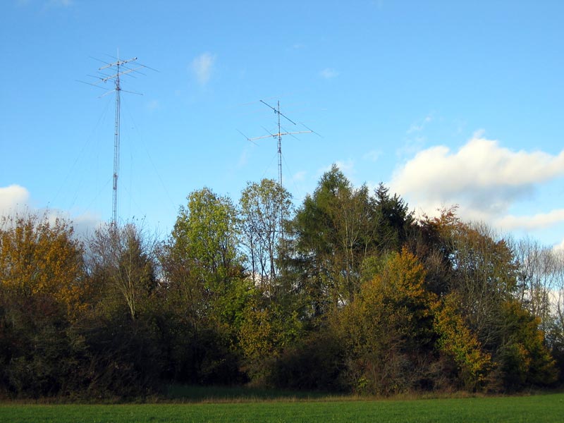
Picture: The complete 80m array for four directions.
The southern radiator is a bit lonely, it will get its own two closer reflectors one day.
Beams on top of our 35 m tall tower worked fine (there is still a boom mounted), but after half a dozen of them we can calculate an average lifetime of 1,5 years. In the winter at our elevated location we have periods with ice load and heavy gales at the same time. As long as we do not find a really robust horizontal solution we have to use a vertical array also on 40 m.
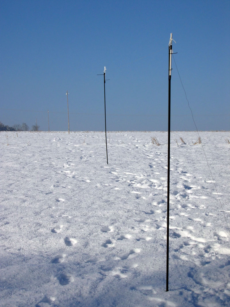
The array was kept as simple as possible. Cheap fishing rods fixed to wooden poles holds the vertical wires. With the groundnet existing we could find a feeding resistance of below 40 Ohms everywhere for a single element (and also no resistance below 30 Ohm, contrary to the strong interaction of 80m verticals with the lattice towers).
The array elements are more or less buried into bushes and trees. We measured a sharp increase of the feedpoint impedance when the element came closer than 1 m to a thicker tree (it then acts as isolator). So we kept the elements in some greater distance. After that the remaining damping was less than expected.
All in all a vertical array is worth to be built not only right at the sea, it can also outperform horizontal beams at places with a decent chicken wire screen, a free takeoff into directions of slightly sloping ground and to paths with low angle skips.

Sketch of the arrangement of three 2-element aerials
The new triple 2el-40m-array for northwestern directions shows following facets:
Sketch of one single 2-element arials

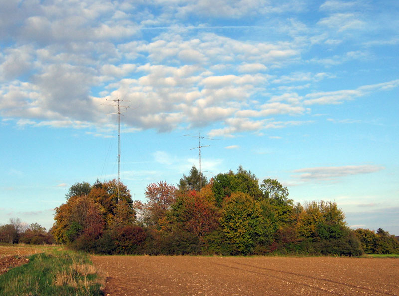
Picture: Ground plan of the aerials
 Connection with capacitor |
 Wooden aerial fixture |
 Combiner |
 Matching network |
 Fixture (wood/fishing pole) |
|
By considering the matching of such an array in detail, one will see, that the 17-to-50-Ohm-transformation works well for a spacing of ca 20m in between the three 2el arrays. For the coax-lengths needed (20,5m) this applies to cables with a velocity factor of 0,66 (RG213) and also for cables with higher VF (so for the yellow ethernet cable 0,82 were taken). For higher spacings the situation becomes more complex. Depending on distance, length and coax (and may be a triangular configuration) the combination impedance can vary in between 10 and 25 Ohm. But things are not critical, trying or better modelling and trying leads quickly to a propper result. With the help of a network analyzer building the LC-network is easy. Experienced OMs can do the job with the TX (put on lowest power), SWR-Bridge and (paralled) low inductive resistors. In this case they begin with a bigger screwdriver handle and 4 windings of enamelled copper wire arround. Than they put the coil in between the bridge and the resistor. With capacitors (with totally something in between 400 or 700 pf) from the coil-bridge-connection to ground and by varying the coil they can soon find a propper match.
 Simple L-C-network to match impedance |
 Coil calculation |
 Azimuth plot simulated with EZNEC/4 |
 Elevation plot simulated with EZNEC/4 |
The first maybe naive 40 m "yagi-alternative" was a triangular array for six directions with three exctended elements (Lamda/4 + phase reversion ladder line + lambda/2) grouped arround the tall tower. After contests Stefan DL1IAO used to name it a dummy load. Today the ground mounted array with lamda/4 elements indeed proves to be better in 90 percent of the time. When the farmland arround become dry in the summer, the difference is even greater (because radiation of the taller array does not get so much help by the groundscreen).
But in few cases it beats everything. Extensive comparisons with a station with a 4 el full size yagi 40m high showed the array to be 10 dB down at the US east coast. On the other hand singular midwest-stations reported 10 dB more for the vertical array. So the very flat radiation with a very slim lobe in the vertical plane seems to be usefull for only more or less rare propagations and pathes.
Because this array is good for surprises and for to extract further experience we kept it alive and say "nice to have". And of course we can combine it with the new array to some directions....
For a short while we used a dipole hanging between the two taller towers. It proved to be a good performer especially for contacts to Berlin (1000 km) and to be a very bad one for all longer distances.
Another attempt was an extended double zepp hanging down from the tall tower with and without additional reflectors. The huge gain towards northwest calculated by EZNEC was confirmed by Englishmen, but not by US-stations. Lesson: At our place a horizontal 40m antenna has to be completely and not partially more then 30m up..
The same was true for a horizontal 2el delta loop hanging from the tower. Perfroming well for northern caribian sea, the takeoff angle for US was definitivly to high.
A long time we resisted from publishing anything else about our antennas. They were built for a unique situation with three lattice rather closed towers on a lot with a certain size and a certain terrain arround. Nevertheless may be the one or other can extract a motivation for an own individual antenna-project, which will lastly provide much more fun than brute force and cheating....
We use NEC 4.2 to simulate and optimize the aerials.
Input and representation is done with 4NEC2.
NEC 4.2 (Numerical Electromagnetic Code), written by Gerald Burke, is a popular antenna modeling code for wire and surface antennas and scatterers. Models can include wires buried in a homogeneous ground, insulated wires and impedance loads. The code is based on the method of moments solution of the electric field integral equation for thin wires and the magnetic field integral equation for closed, conducting surfaces.
We are using buried wires in our simulations together with Sommerfeld-Norton equations. We do use the measured values of conductivity and permittivity. Please see below.
Animation of NEC4-Modell
Radiation patterns tuning the tower to be reflector.

Radiation patterns using sloping wire acting as parasitic reflector.

Sweep of "C" at tower (beeing reflector). We use 250pF in reality!
Chart of gain in this sweep.
We have a second sloping wire in south-east of the tower which is used in the same way to have two additional directions (north-west and south-east). This system does work the same way as descibed one with same results.
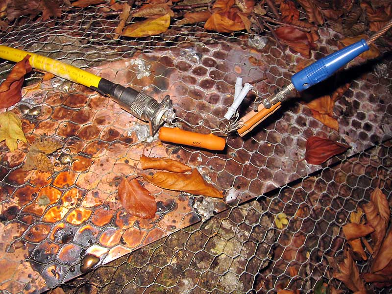
On the 1st of November 2010 we have measured the surface of the earth conductivity and permittivity with high frequency and have found out completely surprised that the conductivity is extremely high. This is probably caused by the strong fertilization of the fields all around.

The measurement took place at two places directly beside the aerials.
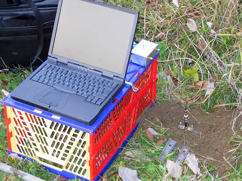
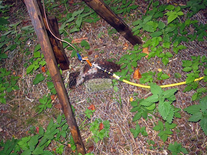
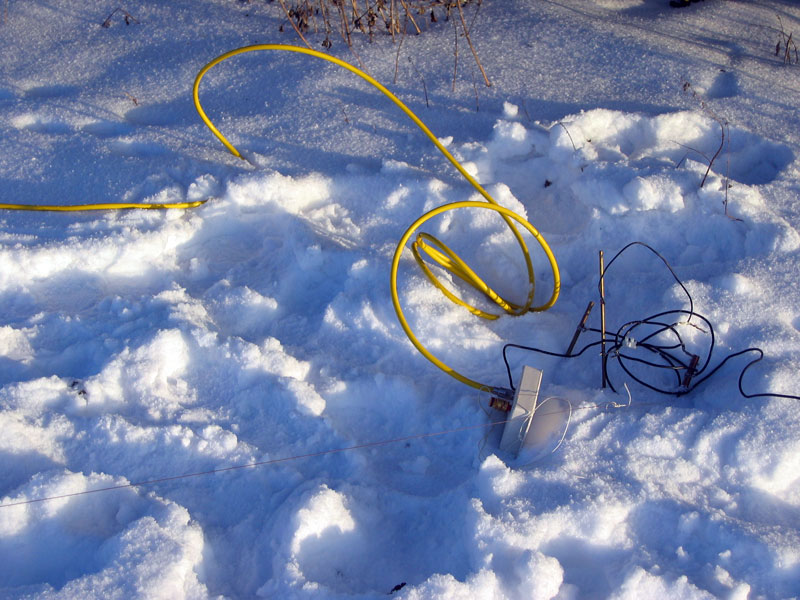
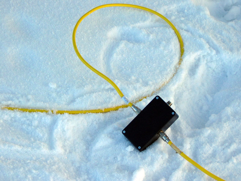
Laptop with vector networkanalyzer (DG8SAQ).

The picture shows the end of the two-wire line in the ground.
| Frequency [Mc] | ε | σ [mS/m] |
|---|---|---|
| 1.8 | 59.4 | 46.6 |
| 3.6 | 51.5 | 48.5 |
| 7 | 43.7 | 53.3 |
| 14 | 34.9 | 66.6 |
| 21 | 28.4 | 95.6 |
Now with these measuring values we also understand the incredibly good results with the vertical aerials at this location. The ground is like a rice field, at least in summer.
The page "Measurement of the ground conductivity and permittivity with high frequency" of DL1GLH explains the procedure to the measurement and the mathematics more exactly.
 |
 |
 |
 |
|
| Terminating resistor | One of the two Beverages | Feed | Coupling |
 |
 |
 |
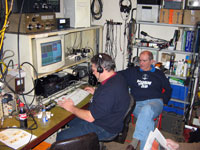 |
 This small film (5mb, MPEG2) shows a conversation on the 27. Dec 2013 with ZL1IU at 80 m. The signal strength amounted up to real S9+35dB (-38dBm)! |
Visitors since 26. Dec. 2009:
The last supplement to website: 17th of January, 2016